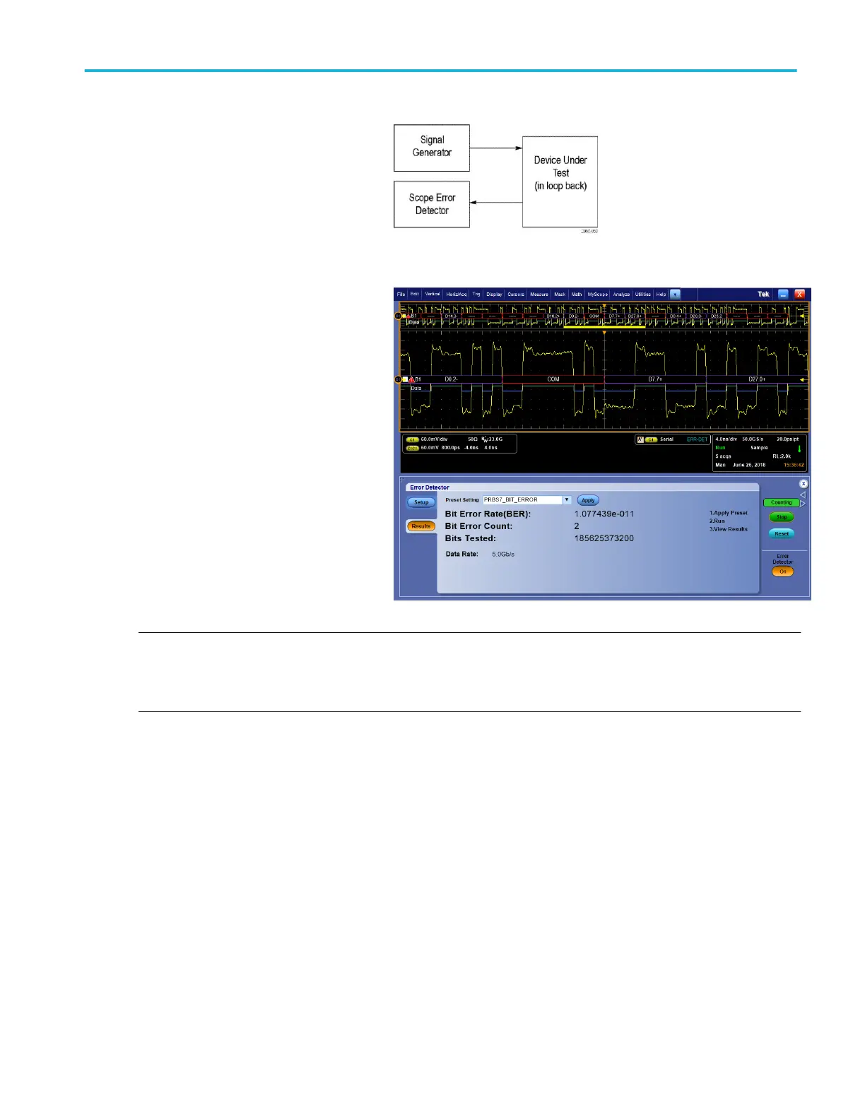
To verify DUT bit error rate performance,
insert the DUT between the Signal Generator
and the Error Detector as shown.
With the DUT inserted between the Signal
Generator and the Error Detector, put your
DUT into loop-back and start outputting the
pattern from the Signal Generator. Press the
Run button to start the Error Detector.
When the Error Detector is enabled, the trigger
type is set to serial trigger. While the Error
Detector is running, the oscilloscope will not
acquire new waveforms unless an error is
detected in the bit stream. When an error is
detected, the oscilloscope will acquire a
waveform containing the bit error. You can use
additional oscilloscope channels to
simultaneously probe other signals to debug
the cause of the error.
If a serial bus is defined from Vertical > Bus
Setup, the Decoder will continue to perform
decoding on the acquired waveform even
while the error detector is running. This can
help find the location in the waveform where
the bit error occurred.
NOTE. If the Error Detector loses lock on the signal for some reason (for example, the signal is removed from the input),
synchronization will be lost. When this happens, the oscilloscope's waveform acquisition will be operating in free run because the
trigger system is no longer synchronized. To resynch the trigger system to the signal and resolve this issue, select Edit > Clear
Data from the Main menu. This will force the trigger system to resynch with the signal and you can resume normal operation.
Analyzing waveforms
DPO70000SX Series User 151
 Loading...


