The oscilloscope waveform display does not
update while the error detector is running
unless a bit error is detected. When a bit error
is detected within the trigger system, a trigger
is generated to capture the waveform data
associated with the bit error event.
If you are using one of the supplied AWG
setup files, you can press the Force Event
button on the AWG to induce an error in the
signal to verify the operation of the Error
Detector. These AWG setup files are located
in Windows in the directory C:\Users\Public
\Tektronix\TekScope\ErrorDetector\AWG.
Alternatively, you can verify operation by
disconnecting and reconnecting the signal.
There will be massive errors when the signal is
disconnected, but after the signal is
reconnected the Error Detector will clear the
error counts and rates and resume testing.
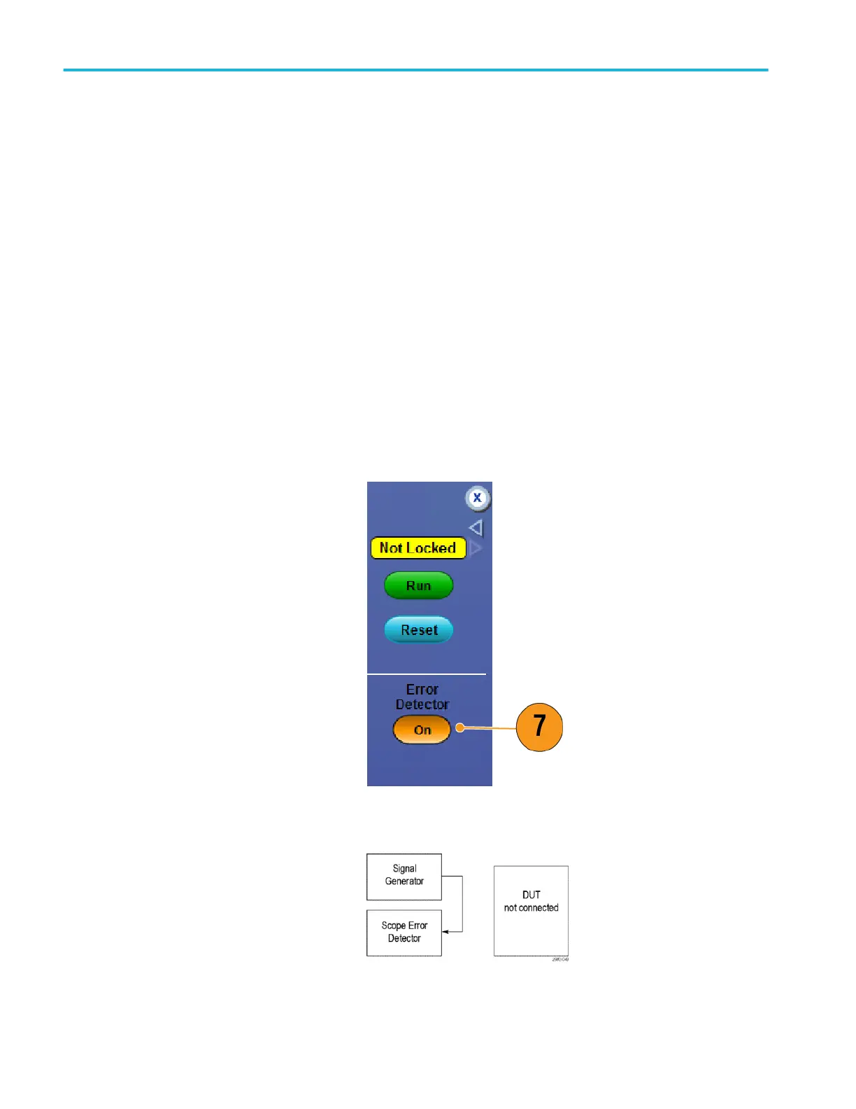
7. Press the Error Detector On/Off button to
end the error detector session.
There are several cable arrangements you can use with the Error Detector. The first cable setup allows you to verify Error
Detector operation.
Connect the cabling as shown to verify Error
Detector operation.
Analyzing waveforms
150 DPO70000SX Series User
 Loading...


