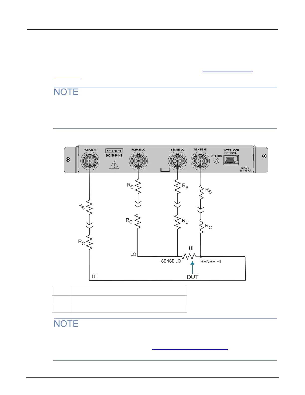
The contact check function also detects open circuits that may occur when a four-point probe is
misplaced or misaligned. This relationship is shown schematically in the figure below, where R
C
is the
resistance of the mechanical contact at the DUT, and R
S
is the series resistance of relays and cables.
Contact check requires both force and sense connections. Refer to 4-wire remote sensing
connections (on page 4-10) for information.
When you are using the 2601B-P-INT, the signals from the SMU are routed through a solid-state
multiplexer that adds an additional 25 Ω to 30 Ω to each of the SHI and SLO paths. Therefore, the
minimum resistance measured for either SHI or SLO when using the 2601B-P-INT is
approximately 25 Ω.
Figure 48: Contact check measurement connections to 2601B-P-INT
The contact check function is not available if the pulser is enabled. If you need to use the contact
check function in a pulser application, you can disable the pulser, run the contact check
measurements, then enable the pulser. See Example 1: Ten-point pulse sweep (on page 4-28) for
an example that shows how to run contact check before running a pulser application.

 Loading...


