To install the 2601B-P-INT:
1. Remove power connections from the 2601B-PULSE.
2. On the rear panel of the 2601B-PULSE, remove the screws to the left of the CHANNEL A:
DC/PULSE terminal strip and to the right of the CHANNEL A: DC terminal strip. Save the screws
for operation with the 2601B-P-INT uninstalled. Screw locations are shown in the following figure.
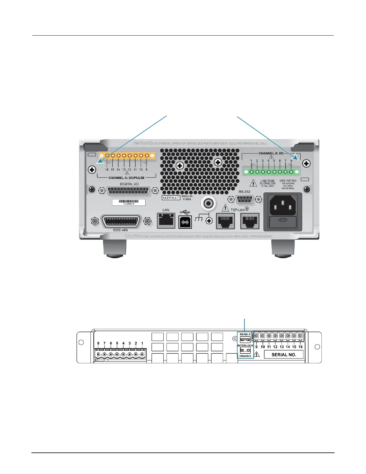
Figure 10: Remove screws from 2601B-PULSE rear panel
3. On the terminal strip panel of the 2601B-P-INT, position the INTERLOCK jumper. Use
needle-nose pliers to position the jumper in the ENABLE slot if you are using an interlock or
DISABLE if you are not using the interlock. The INTERLOCK jumper is shown in the following
figure.
Figure 11: INTERLOCK jumper on the 2601B-P-INT Interlock Box terminal strip panel
4. Align the terminal strip panel of the 2601B-P-INT to the terminal strips on the rear panel of the
2601B-PULSE.
5. Press the 2601B-P-INT connections firmly onto the terminal strips on the rear panel of
the 2601B-PULSE.

 Loading...


