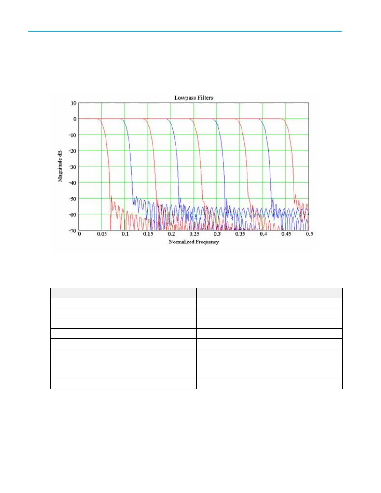
Low pass filters. The following graphs show the available set of low pass filters. Their normalized frequency response is shown
from 0 to ½ the sample rate. These filters will operate at any sample rate with cutoff frequency scaled as shown below on the
graphs. The filters have normalized cutoff frequencies of 0.05, 0.1, 0.15, 0.20, 0.25, 0.3, 0.35, 0.40, and 0.45. Stop band
rejection is typically between –50 and –60 dB.
Figure 25: Frequency response of the available low pass filters
The following table lists the available low pass filters:
File name Normalized cutoff frequency
lowpass_0.05bw.fl 0.05
lowpass_0.10bw.flt 0.10
lowpass_0.15bw.flt 0.15
lowpass_0.20bw.flt 0.20
lowpass_0.25bw.flt 0.25
lowpass_0.30bw.flt 0.30
lowpass_0.35bw.flt 0.35
lowpass_0.40bw.flt 0.40
lowpass_0.45bw.flt 0.45
Oscilloscope reference
786 DPO70000SX, MSO/DPO70000DX, MSO/DPO70000C, DPO7000C, and MSO/DPO5000B Series
 Loading...