Select the bus decode method
From the Bus Setup window, select the Display tab.
To use
■
Scroll through the Bus list and select the bus to configure.
■
Click the Busform Decode drop down list and select the method to interpret and display the data from the bus.
Behavior
The instrument displays the busform based on the selected decode method. Available decode methods vary with the selected
bus.
■
Hex causes the instrument to decode and display the bus as a hexadecimal value.
■
Binary causes the instrument to decode and display the bus as a binary value.
■
ASCII causes the instrument to decode and display the bus as an ASCII value.
■
Mixed causes the instrument to decode and display the bus frame and address in decimal. You have the option to display
the data either as a hexadecimal or an ASCII value. Mixed displays the data type as symbols, and it displays the virtual
channel and word count in decimal. All other fields are displayed in hexadecimal.
Mixed decoding methods like symbol for DT (Data Type MIPI element), decimal for VC (Virtual Channel MIPI element) and
WC (Word Count MIPI element), and hexadecimal for all other fields are available for MIPI DSI-1 serial bus type.
What do you want to do next?
Learn more about bus setups.
Learn about bus configuration.
Learn about digital setups.
Learn about the symbol file format.
Learn to view the bus packets.
View bus packet
NOTE. Serial Bus Channel Type is only available on instruments with option SR-COMP.
From the Bus Setup window, select Serial from the Bus Type list and then select the RS-232 in the Config tab.
To use
■
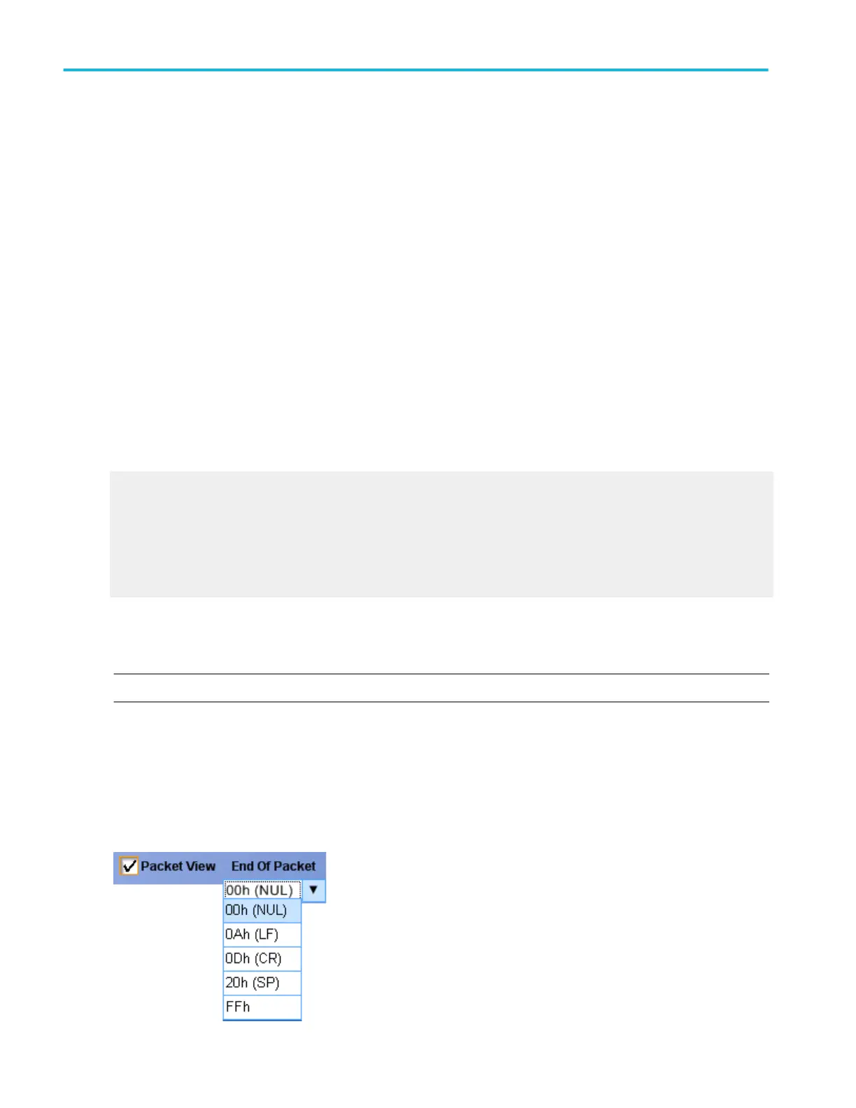
Select the Packet View check box in the Config tab. The bus display shows decoded packet level information on the bus
and displays the value in hexadecimal, binary, or ASCII in the bus waveform.
■
Select one of the available options in the End of Packet list.
Bus setups
158 DPO70000SX, MSO/DPO70000DX, MSO/DPO70000C, DPO7000C, and MSO/DPO5000B Series
 Loading...