Reference
Options Settings C om men ts
Coupling AC, DC, Noise Reject, HF
Reject, LF Reject
Selects the components of the trigger
signal applied to the trigger circuitry;
(See page 112, Edg
e Trigger.)
More Use to switch between submenu
pages
1
Available only on a 4-channel oscilloscope.
Trigger Frequency Readout
The oscilloscope counts the rate at which trigger events occur to determine trigger
frequency and displays the frequency in the lower right c orner of the screen.
Key Points
Trigger When. The pulse width of the source must be ≥5 ns for the oscilloscope to
detect the pulse.
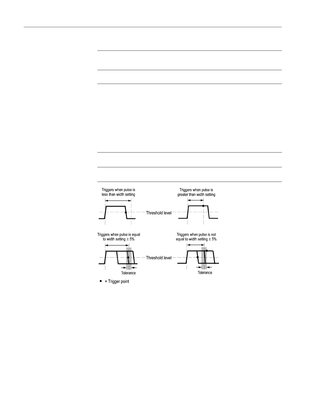
When options Details
=
≠
Triggers the oscilloscope when the signal pulse width is equal to or
not equal to the specified pulse width within a ± 5% tolerance
<
>
Triggers the oscilloscope when the s ource signal pulse width is less
than or greater than the specified pulse width
Refer to the Application Examples chapter for an example of triggering on
aberrant pulses. (See page 54, Triggering on a SpecificPulseWidth.)
Knobs and Buttons
Trigger Level knob. Use to control the Trigger Level.
Set to 50% button. Use the Set to 50% button to quickly stabilize a waveform.
The oscilloscope automatica
lly sets the Trigger Level to be about halfway between
the minimum and maximum voltage leve ls. This is useful when you connect a
signal to the Ext Trig BNC and set the trigger source to Ext, Ext/5, or Ext/10.
116 TPS2000B Series Digital Oscilloscope User Manual