Getting Acquain
tedWithYourInstrument
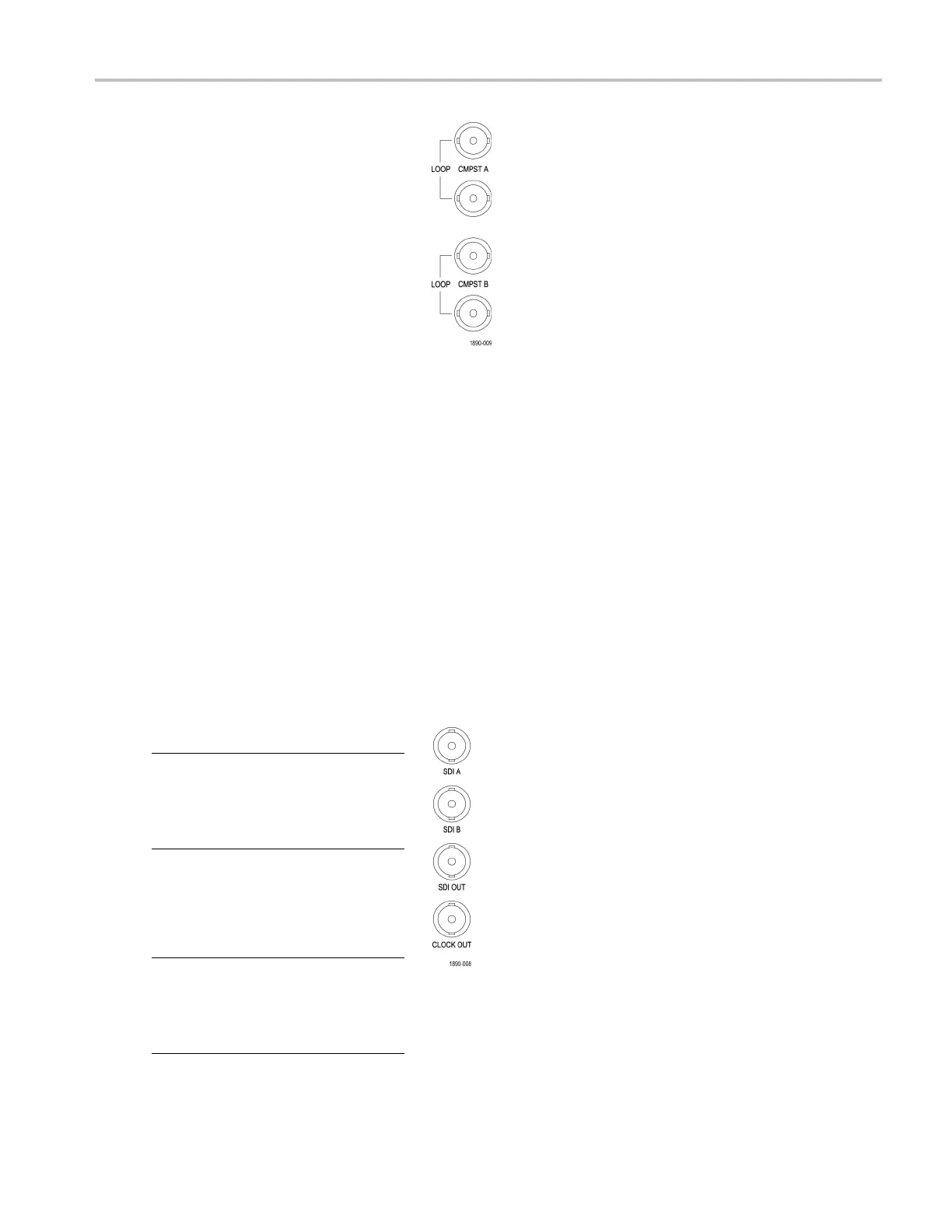
2. Connect analog composite signals to
the A or B Composite inputs at the
rear panel. (O
n Option CPS equipped
instruments only.)
3. For the composite inputs, terminate the
loop-through input properly at the rear
panel for any
inputs that are not routed
to another device.
Option CPS
4. Press the Input button corresponding
to the input that you want (SDI Input A
shown).
5. Select a tile and measurement in which
to display the input.
3 Gb/s Input Monitoring
With Option 3G installed, this instrument provides support for monitoring and measuring 3 Gb/s single link signals in 1920 x
1080p/50/59.94/60 formats. If your instru ment also has Option JIT, it can generatea3Gb/ssinglelinklooptestsignalas
well as m
onitor a 3 Gb/s single link signal.
Three t
ypes of signals can be generated in Level A and Level B 3 Gb/s: 75% bars, 100% bars, and pathogenic. If you want
to use a pathogenic signal, use Level A, if possible. For more information about 3 Gb/s signals, see the appropriate SMPTE
standard. The following procedures show you how to set up your instrument for 3 Gb/s monitoring and generation.
ToSetUpanExternal3Gb/sInput
NOTE. The factory default sets instruments
with Option JIT so that the 3 Gb/s loop out
test signal is OFF. If it has been turned ON,
you need to turn it OFF before an external
3 Gb/s signal can be used.
1. Connect a 3 Gb/s video signal to the SDI
A input at the rear panel.
2. Select a tile and measurement in which
to display the input.
NOTE. If your instrument does not have
Option JIT, you can use a second WFM with
Option JIT to generate the 3 Gb/s signal.
Connect the SDI OUT of the generating unit
to the SDI A of the monitoring unit.
Options EYE/PHY, 3G
Waveform Monitors Quick Start User Manual 23
 Loading...


