EAR-Controlled Technology Subject to Restrictions Contained on the Cover Page.
Page 5
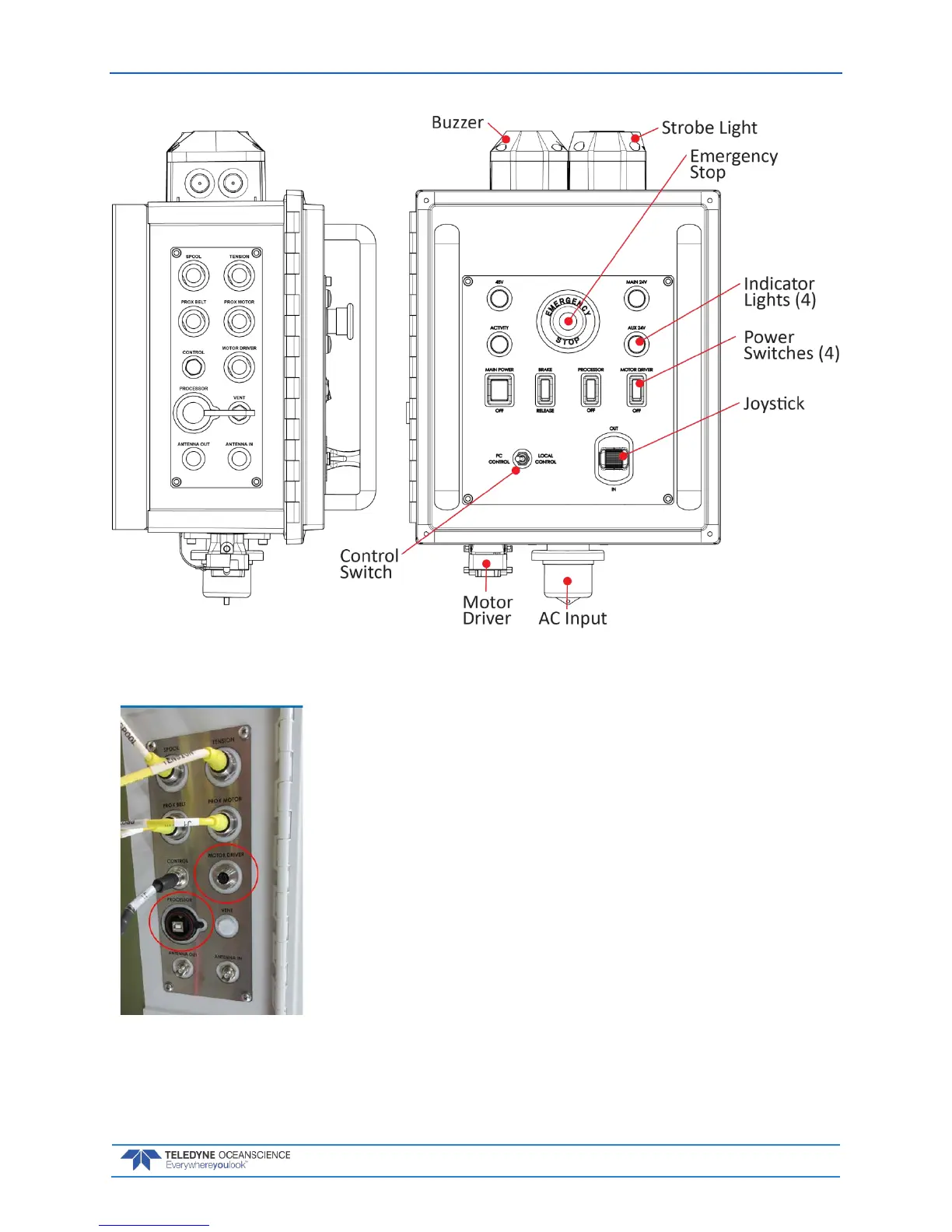
Figure 3. Control Module Overview
• The top four connectors are latching non-threaded push-pull
types.
• The Control and Antenna connectors are threaded and screw
on.
• Ensure that connectors are fully-seated; otherwise water re-
sistance may be compromised!
• Connectors circled in red are used only in special circum-
stances and are normally left disconnected. Make sure the
caps are on during a deployment to protect the connectors.
 Loading...