Resolving Fault Conditions
PROBLEM: The Control Module does not appear to be powered.
INDICATIONS: One or more LEDs on the Control Module are off.
DESCRIPTION: For normal operation:
The green 48V, Main 24V, and Aux 24V LEDs must all be lit
The green Activity LED must be blinking
The red Emergency Stop LED must be lit
An unlit LED indicates a lack of power to the corresponding subsystem, or a failure of the LED itself
(unlikely).
BASIC REMEDIES: (ensure that ALL of the following are satisfied):
Verify that the control module is receiving sufficient AC power. See Electrical Requirements sec-
tion.
Verify that Main Power and Motor Driver Switches are in the On position (upper halves are de-
pressed).
Ensure that Emergency Stop switches on the Control Module and Interface Module are released
in the up position.
Ensure that the Control Cable is connected between the Control Module and the Interface Mod-
ule. Disconnecting this cable is equivalent to pressing an Emergency Stop; this cable must be
connected for normal operation.
ADVANCED REMEDIES: (to be attempted if Basic Remedies do not resolve the issue):
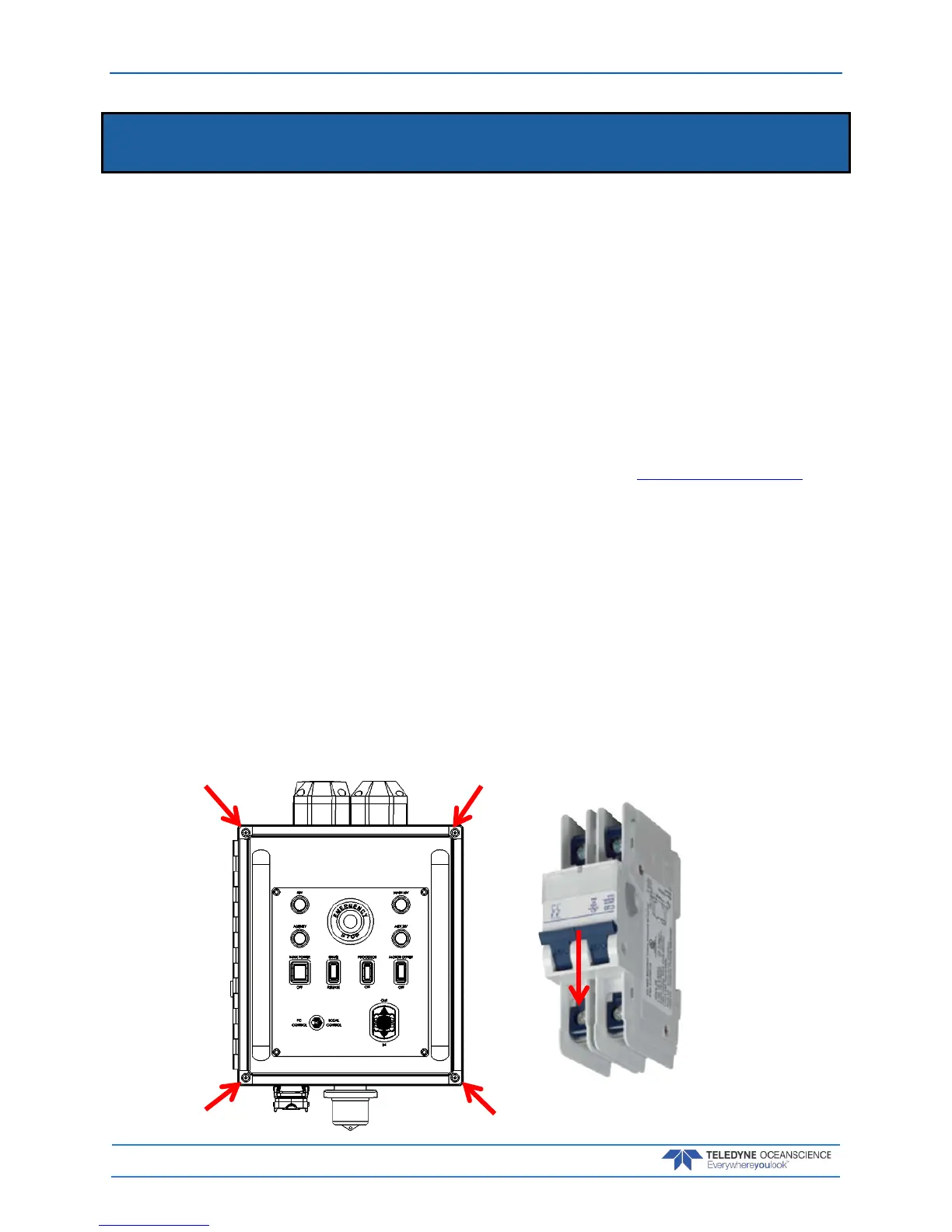
1. Remove the four (4) Philips head screws on the lid and swing the cover open
2. Check the circuit breaker position is in the ON position, DOWN. The figure shows the circuit
breaker in the OFF position, UP.