Installation and Programming Manual - СА62 Alarm Control Panel 17
In1 - Input for resetting wireless re detectors (time for reset ≥ 2 seconds), the active state towards GND is 0V; In2 -
Input for wireless siren control (time for reset ≥ 2 seconds), the active state towards GND is 0V; In3 - Used only in case
RC102TE remote control is enrolled to UWE432 receiver module; this is an input for monitoring of the control panel
status; Out1 - Relay output (NO) for Low Battery and Lost Device state of wireless devices; Out2 - Relay output (NC) for
TAMPER state of wireless devices and the UWE432 box; Connect to a TAMPER type zone of the control panel.
More information about UWE432 functions and programming you can nd in its installation instructions.
2.14 Powering up the CA62 Alarm Control Panel
The system should be powered-up only after it is installed and all necessary devices have been connected - control
panel, keyboard, detectors, etc.
Follow the next installation procedure when power-up the CA62 system for the rst time:
➢ Set the JPRG jumper (Figure 5) on CA62 control panel, in order to congure the control panel default pa-
rameters (the factory settings).
ATTENTION: The CA62 alarm control pane supports 4 different default congurations. With every full hardware
system reset (jumper JPRG is set) the parameters for default conguration 0 will be set. The special of the
default conguration 0 is that all zones in the system are disabled (the 0.Unused type is set for all), the zone
balancing is with one resistor in the circuit and so on. For details for settings of the default system congura-
tion 0, see SECTION 2 - Programming.
➢ Supply 220V mains power. The keyboard emits a short sound signal or series of short beeps according
the used model. In case of a LED keyboard the light-emitting diodes on the display blink. When a LCD
keyboard is used the display will light up in blue or orange.
➢ Remove the JPRG jumper. In normal operation mode - all detectors in the security system are inactive
and there are no violated anti-TAMPER chains - the RDY LED lights up in green. The station now has been
programmed with the default conguration 0.
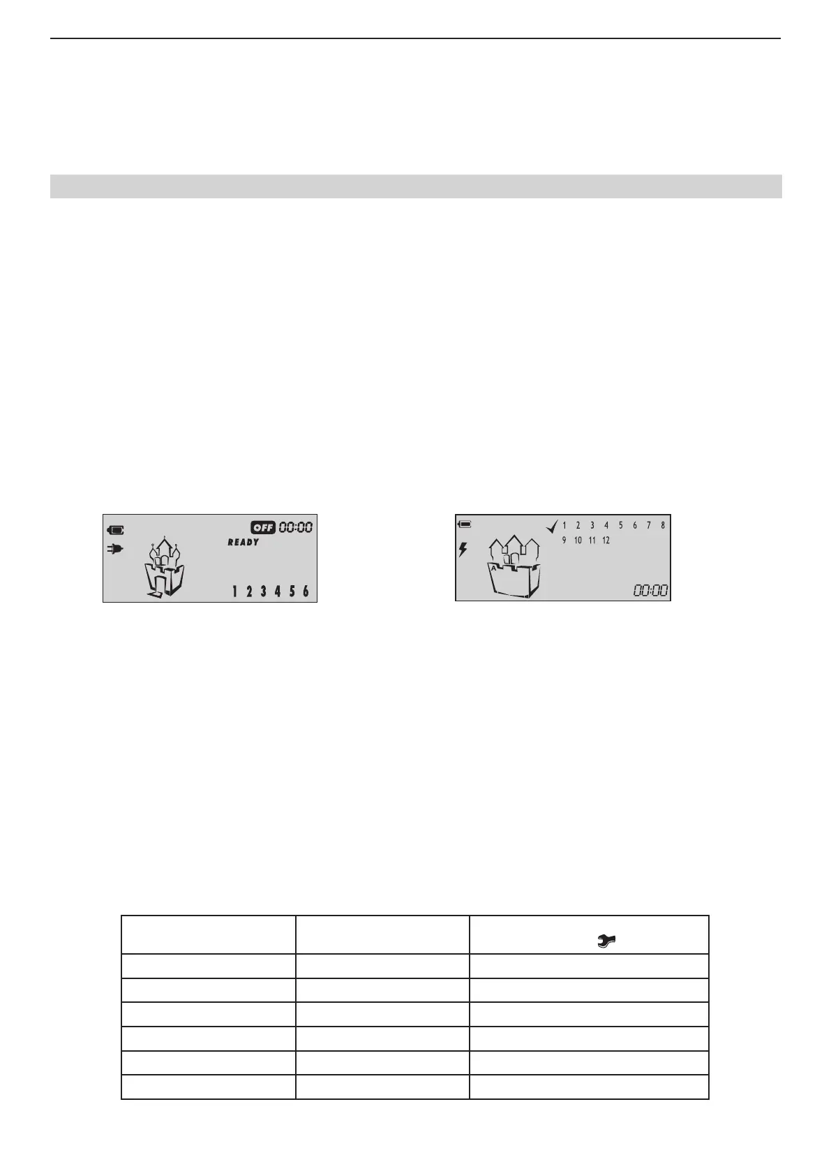
If you operate with LCD keyboard the display is looking different according the model:
Models: Model:
LCD62, LCD63SE
LCD62B, LCD64
LCD63
➢ Use the red (+) and black (-) cables to connect the battery to the station.
All light-emitting diodes will blink and a sound signal will be heard where the keyboard is open or incorrectly connected.
Where there is an open zone or an open TAMPER for any zone, the LED for the respective zone (at LCD keyboards the
zone number is enclosed in brackets) together with the MEMORY or TAMPER LEDs on the display will light up (at LCD
keyboards lights up TRBL LED and symbol "wrench" is blinking).
ATTENTION! An open anti-sabotage chain (TAMPER) in the security system will sound the siren. To stop the
siren enter Manager code 0000. The respective zone LED remains permanently lit whereas the TAMPER LED will
blink. Remove the failure - the TAMPER LED remains permanently lit. Enter code 0000 again to clear the alarm
event from the memory.
2.14.1 Technical Trouble Indication
Any technical trouble in the panel will light up the Trouble indicator (blinking TRBL LED and/ or symbol “wrench” accord-
ing of the keyboard model). To view these problems enter the 0000 manager code and single-press ENTER. The display
will indicate a list of current problems. The indications and their meaning are shown in the table below:
LED Keyboard
LED lighting up
LCD Keyboard
Digit enclosed in brackets
Technical trouble
(LED or symbol
is blinking)
B
(1)
No 220 V power supply
C
(2)
Battery low
D
(3)
Fuse burned
E
(4)
No telephone line
F
(5)
No communication available
G
(6)
Active TAMPER within the system
Trouble mode indication (Technical Trouble)