50 SUPPLEMENTS - СА62 Alarm Control Panel
SUPPLEMENT A - Default programming tables
TABLE 1: Engineer Menu - DEFAULT CONFIGURATION 0, 1, 2 and 3
ADDRESS MENU
DEFAULT CONFIGURATION 0
DEFAULT
CONFIG. 1
DEFAULT
CONFIG. 2
DEFAULT
CONFIG. 3
LED 1 LED 2 LED 3 LED 4 LED 5 LED 6
0.
ENGINEER PARAMETERS AND COMMON SETTINGS
0000 Engineer code (7777) Digit 1 Digit 2 Digit 3 Digit 4 7777 7777 7777
0001 Reset enable NO - LEDs off YES - LEDs on YES YES YES
0002 Default settings Press the keys from 1 to 6 consequently and conrm by ENTER
0003 Partial reset Press the keys from 1 to 6 consequently and conrm by ENTER
0010 Quick ARM enable Part A Part B A and B A and B A and B
0011 Enable ambush code NO - LEDs off YES - LEDs on NO NO NO
0012 Enable keypad block NO - LEDs off YES - LEDs on NO NO NO
0013 Trouble mask 1. AC LOST 2. BATT LOW
3. FUSE
BLOWN
4. NO TEL
LINE
5. COMM
ERROR
6. TAMPER
1, 2, 3, 4,
5, 6
1, 2, 3, 4,
5, 6
1, 2, 3, 4,
5, 6
0014 AC delay NO (Instant indication) - LEDs off YES (Time delayed indication) - LEDs on NO NO NO
0015 Line fault delay Number 00 to 99 min → 00 min. 15 min 15 min 15 min
0016 Bell on Tel Line Fault Part A Part B
0017 Bell on TAMPER Silent TAMPER in DISARM - LEDs off Audible TAMPER in DISARM - LEDs on Audible Audible Audible
0018 AC Time delay entry
A time delay indication for 220 V AC power supply failure in the range 0 - 180 min. The installer sets a
two-digit number from 00 to 18, as every digit corresponds to 10 minutes interval. Defaut → 30 min.
30 min 30 min 30 min
0020 Walk test ZONE 1 ZONE 2 ZONE 3 ZONE 4 ZONE 5 ZONE 6 ZONE 1- 6 ZONE 1- 6 ZONE 1- 6
0021 Keypad test Testing the keyboards indication.
0022 Outputs test PGM1 PGM2 PGM3 PGM4 PGM 1 - 4 PGM 1 - 4 PGM 1 - 4
0023 Comm. Display 1. Dial tone 2. Dialling 3. Wait HS 4. Send data 5. Wait kiss-off 6. All sent Steps 1- 6 Steps 1- 6 Steps 1- 6
0024 Display LOG Viewing the LOG memory.
0025 UDL / Direct UDL 1. Ring 2. Call back 3. Currier 4. Receive 5. Transmit 6. End Steps 1- 6 Steps 1- 6 Steps 1- 6
0026 Comm. HW test 1. Relay 2. Dial tone 3. Low freq. 4. High freq. 5. DTMF “3” Steps 1- 5 Steps 1- 5 Steps 1- 5
0030 Set clock Clock setting (HH:MM). Default at RESET → 00:00.
0031 Set date Date setting (DD.MM). Default at RESET → 01.01.
0040 Chime Enable/ Disable NO - LEDs off YES - LEDs on NO NO NO
0099 Software revision The Engineer can review the number of current software revision of the CA62 control panel at this address.
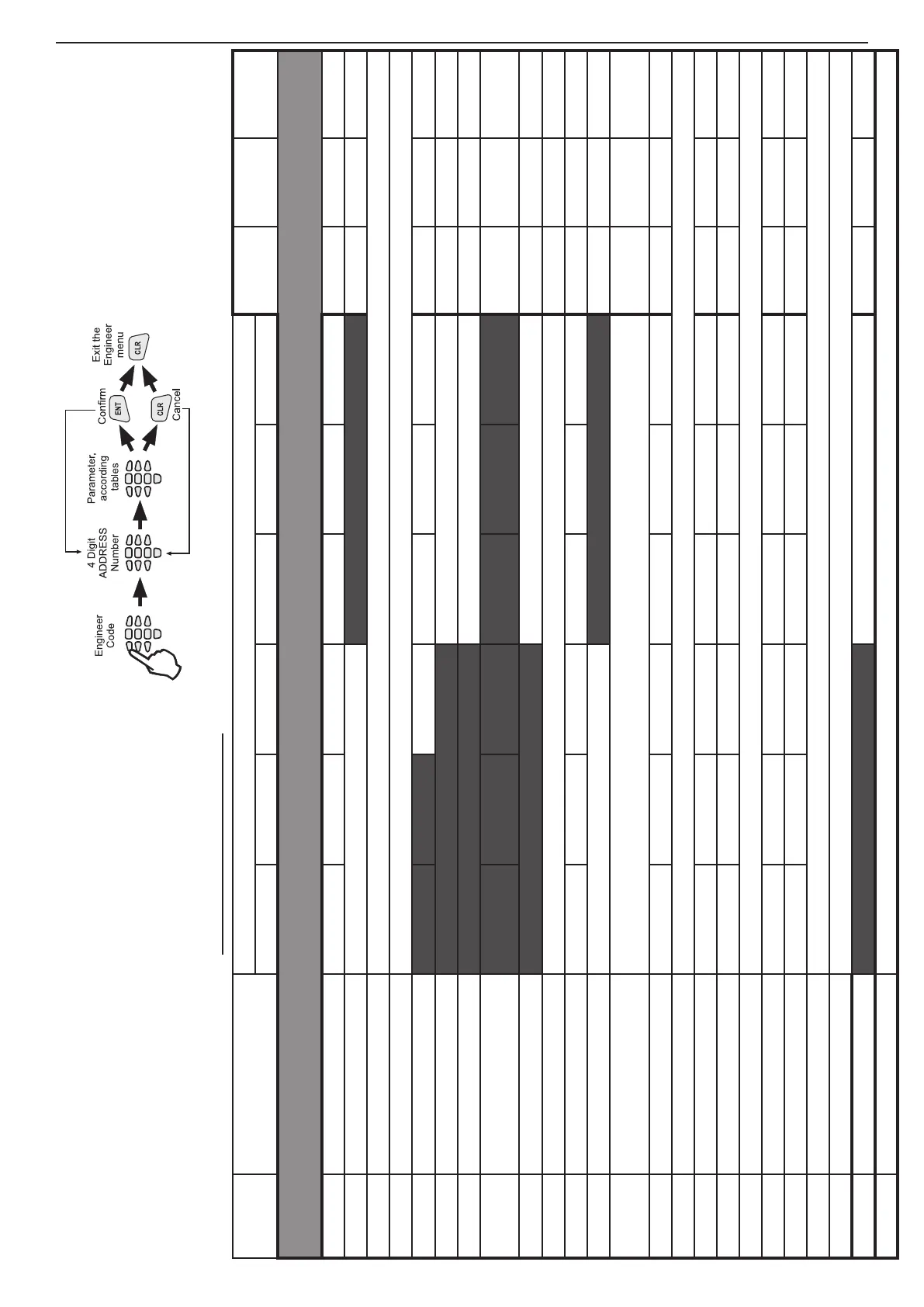
All parameters, attributes, codes and values in the
system are program in one and same way.
Follow the next sequence when program the system: