8 Installation and Programming Manual - СА62 Alarm Control Panel
2.5 CA62 Alarm Control Panel Inputs and Outputs
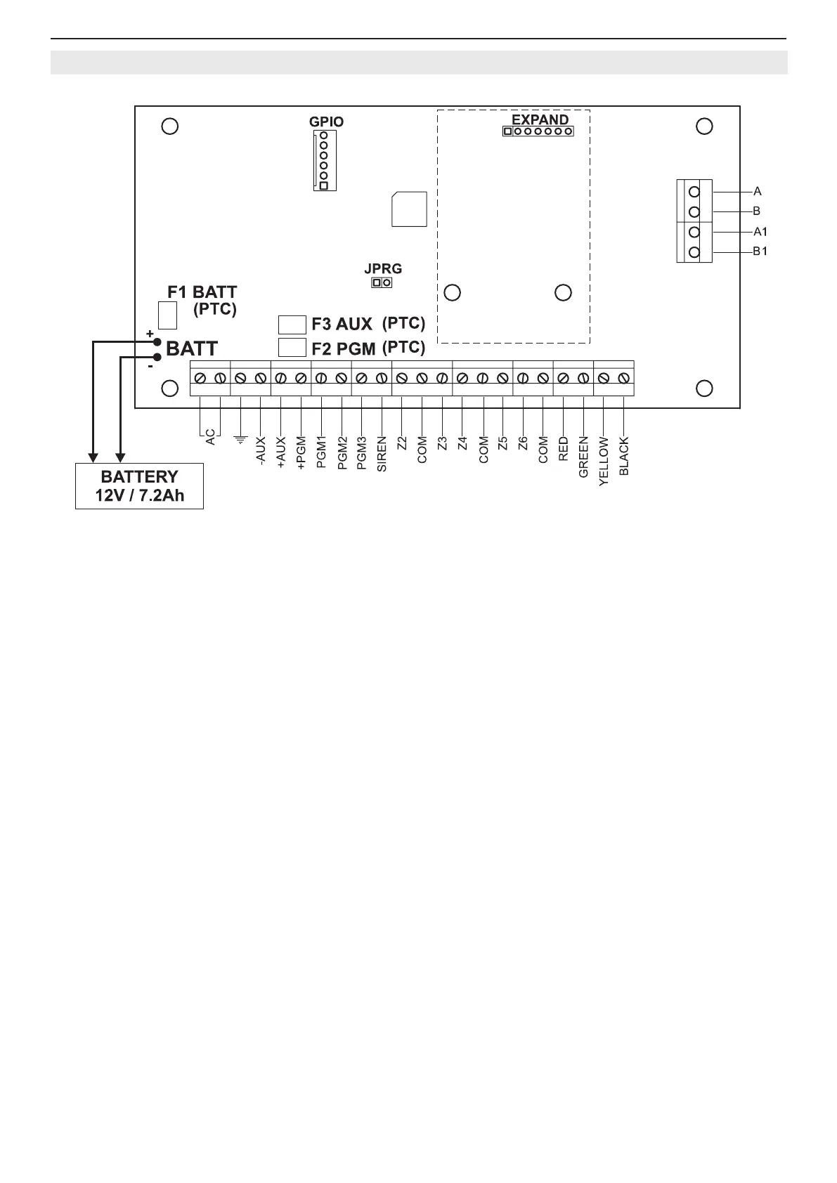
Figure 5. CA62 control panel inputs and outputs.
Terminals description of СА62 control panel:
• AC - Power supply from 17V / 17VA mains transformer
•
- “EARTH”
• AUX - Power supply -PGM for detectors with consumption up to 1А
• +PGM - Power supply for additional devices with consumption up to 1А
• PGM1, PGM2, PGM3 - Programmable outputs
• SIREN - Siren programmable outputs (PGM4 by default)
• Z2, Z3, Z4, Z5, Z6 - Zone inputs (Z1 zone is in the keyboard))
• COM - Common mass of the zones
• A, В - Terminals for telephone line connection
• А1, В1 - Terminals for connecting a telephone set
• RED, BLACK - Keyboard power supply
• GREEN, YELLOW - Interface between the panel and the keyboard
• F1 BATT - Battery fuse 0.75А, Resettable (PTC)
• F2 PGM - Additional device 0.5А mains fuse, Resettable (PTC)
• F3 AUX - Fuse for powering sensors, programmable outputs and keyboards 0.5А, Resettable (PTC)
• BATT - Battery cables for accumulator with parameters 12V / 7.2 Ah
• JPRG - Jumper for hardware RESET and default parameters recovery
• GPIO - Interface connector for programming
• EXPAND - Terminal for expander modules (Voice dialer VD60)