Installation and Programming Manual - СА62 Alarm Control Panel 23
SILENT
Tamper
In case of TAMPER event in the system:
- The LED indication and the internal buzzer of the key-
boards are activated;
- Output TAMPER type is activated (no alarm signal
from outputs ALARM and SIREN type);
- No alarm message is sent to monitoring station.
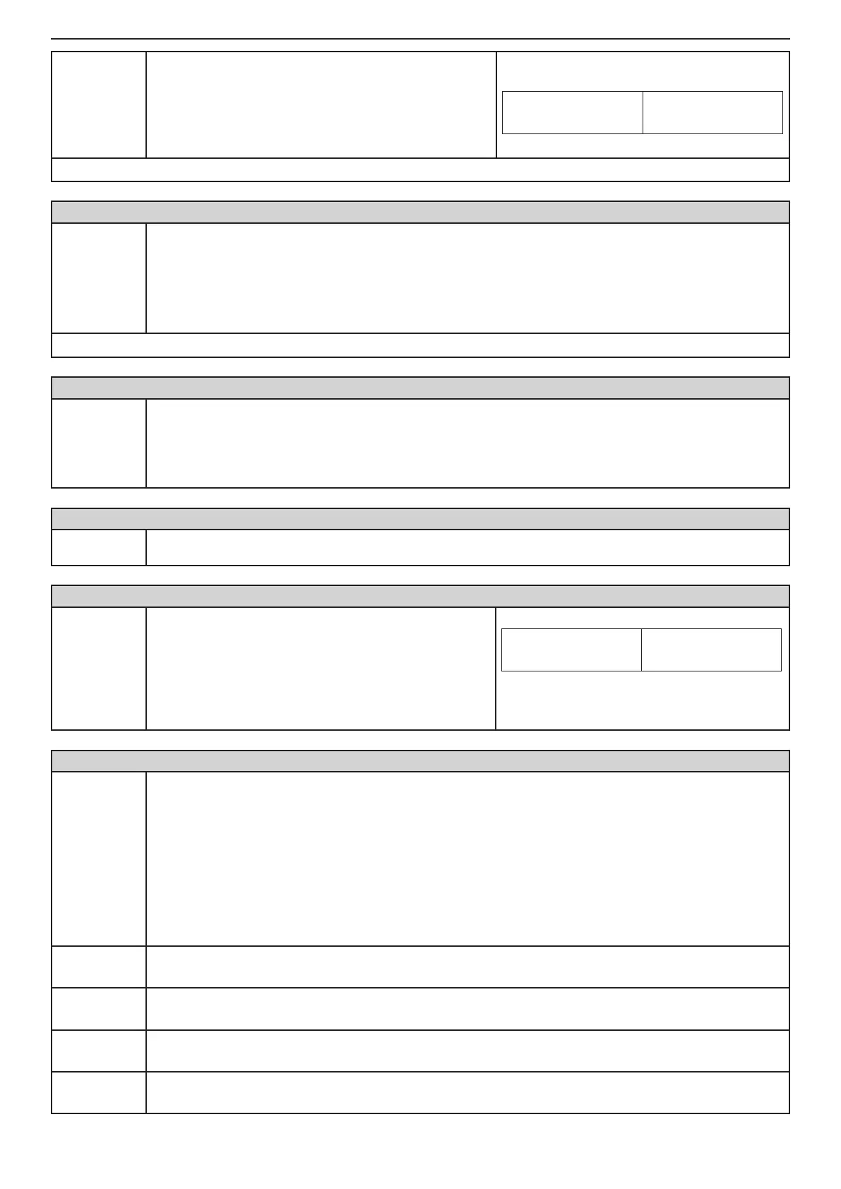
Indication
LED
LCD
1 2 3 4 5 6
Default settings
- AUDIBLE Tamper
ADDRESS 0018 - TIME DELAY INDICATION FOR 220 V AC POWER SUPPLY FAILURE
Time delay
indication
for 220 V AC
power sup-
ply failure
A time delay indication for 220 V AC power supply failure is set on this address. The time delay is in
the range 0 - 180 min.
The installer sets a two-digit number from 00 to 18, as every digit corresponds to 10 minutes interval.
Note: You can program the time delay only when the "YES" parameter is set on address 0014.
Example: For 10 minutes time delay set 01; for 20 minutes time delay set 02; for 30 minutes - 03; for
120 minutes - 12, etc.
Default settings
- 3 (30 minutes)
ADDRESS 0020 - TEST FOR PROPER ZONE OPERATION (WALK TEST)
Walk Test
Enables functional test of zones. The respective light-emitting diode (LED keyboard) or a number of a
zone (LCD keyboard), blinks while the zone is activated (open) in this mode. During the test every zone
activation is accompanied with "Chime" sound signal and with continuous sound for "reject" - open
TAMPER zone. As long as there is an open tamper zone its respective number remains active - per-
manently lit LED (LED keyboard) or enclosed in brackets (LCD keyboard).
ADDRESS 0021 - KEYBOARD TEST
Keyboard
test
Checks the serviceability of the keypad light-emitting diodes and buzzer.
ADDRESS 0022 - PGM1, PGM2, PGM3 and SIREN (PGM4) PANEL PROGRAMMABLE OUTPUT TEST
Output test:
1 PGM1
2 PGM2
3 PGM3
4 SIREN
(PGM 4)
Serviceability tests of programmable outputs is carried
out by pressing a numbered button which corresponds
to the programmable output.
The respective number on the LED or LCD display is
activated and the output passes into a low level - 0V.
Pressing the button with the corresponding number a
second time renders the output into a high level - 12V.
Indication
LED
LCD
(1) (2) 3 (4) 5 6
Example: To the outputs PGM1, PGM2 and
SIREN is set a low level - 0V. To the output
PGM3 is set a high level - 12V.
ADDRESS 0023 - DISPLAY COMMUNICATOR
Display
communica-
tor
The performance of the communicator can be directly monitored at this address.
Note: Before starting the monitoring of the communicator performance you have to enter a telephone
number at ADDRESS 6010.
The ARM button causes test transmission from the communicator to the central station and from the
voice dialer to assigned telephone numbers. The 0 button aborts any running communication and de-
letes the queue of events to be sent.
The meaning of the symbols is given below, as the "active state" means permanent lighting of the
LEDs (LED keyboard) or enclosed in brackets number (LCD keyboard).
After communication has been successfully completed the keyboard emits a sound signal. The CLEAR
button exits ADDRESS 0023.
1: Dial Tone
• LED blinks / ( ) at LCD - searching for a “dial” free tel. line
• active state /
or (1)/ - a “dial” signal has been identied
2: Dialing
• LED blinks / ( ) at LCD - dialing the telephone number
• active state /
or (2)/ - telephone number has been dialed
3: Wait HS
(handshake)
• LED blinks / ( ) at LCD - expecting a HAND SHAKE from central station
• active state /
or (3)/ - the necessary handshake signal has been identied
4: Send data
• LED blinks / ( ) at LCD - transmitting data to central station
• active state /
or (4)/ - the current data has been transmitted