Installation and Programming Manual - СА62 Alarm Control Panel 33
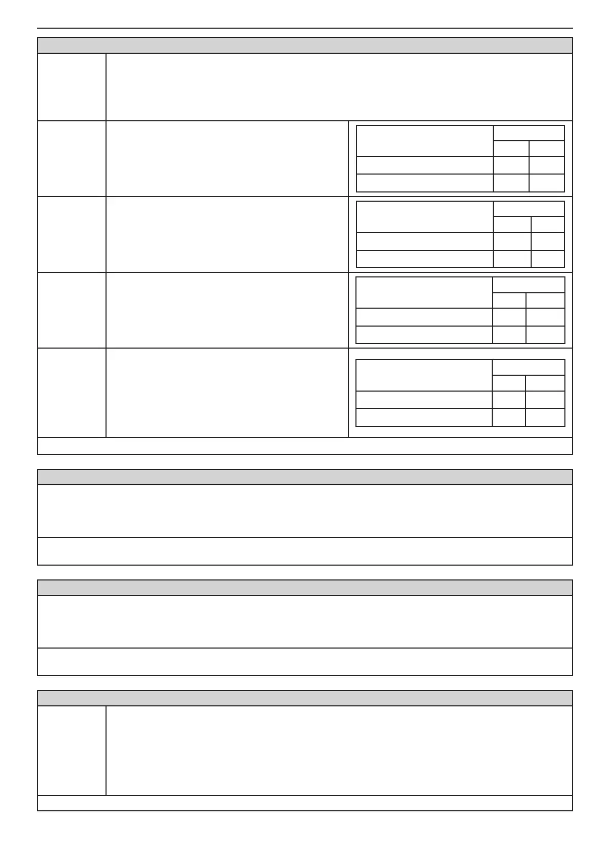
ADDRESS 2026 - TYPE OF BALANCING FOR ZONE 2
Type of
balancing for
ZONE 2
The type of ZONE 2 balancing is selected at this address. Every consecutive pressing of a digital but-
ton alternatively changes the type of balancing. Display indications are given in the tables below.
The doubling zone type connection can be realized to ZONE 2 - see the Figure 6 c.
Note: When connecting one re detector to the zone do not assign any type of balancing for it. When
connecting 2 re detectors to the zone you have to assign the 4.Doubling attribute!
1. EOL
Connecting of balancing resistor.
With or without TAMPER in the circuit.
EOL Connecting
Indication
LED LCD
Without TAMPER
1
With TAMPER
(1)
2. Fast/
Regular
Programmable sensitivity of the zone between 10
and 250ms.
Sensitivity
Indication
LED LCD
Regular (250ms)
2
Fast (10ms)
(2)
3. Power-up
delay
The zone will be bypassed for a 120 second pe-
riod after power-up of the system (that eliminated
the false alarms in the initial power-up of the control
panel).
Power-up delay
Indication
LED LCD
Without zone bypass
3
Zone bypass (120 sec)
(3)
4. Doubling
Doubling zone connection. The parameter is as-
signed when the doubling zones connection is real-
ized in the system. Activating this parameter will dis-
able the setting of 1.EOL attribute at the beginning
of this address, as considers that the connecting of
balancing resistors in this case is with tamper in the
circuit.
Mode
Indication
LED LCD
Single zone
4
Doubling zone
(4)
Default settings
- no attribute is set
ADDRESS 2030 ... 2036 - ZONE 3 PROGRAMMING
The programming is the same as that at ADDRESS 2010 - 2015, as the type, attributes (parameters 1, 2 and 3, AUX)
as the attachment of ZONE 3 are assigned.
The doubling zone type connection can be realized to ZONE 3 - see the Figure 6 c. The ZONE 3 corresponds to ZONE
9. The type of connection can be programmed at ADDRESS 2036 with setting the "4.Doubling" attribute.
Default settings - type Unused; ATTRIBUTES 1 - AUTOBYPASS and BYPASS; ATTRIBUTES 3 - Disarm Enable;
ATTRIBUTES AUX - 00. 24 h Burglary; Attachment - PART А
ADDRESS 2040 ... 2046 - ZONE 4 PROGRAMMING
The programming is the same as that at ADDRESS 2010 - 2015, as the type, attributes (parameters 1, 2 and 3, AUX)
as the attachment of ZONE 4 are assigned.
The doubling zone type connection can be realized to ZONE 4 - see the Figure 6 c. The ZONE 4 corresponds to ZONE
10. The type of connection can be programmed at ADDRESS 2046 with setting the "4.Doubling" attribute.
Default settings - type Unused; ATTRIBUTES 1 - AUTOBYPASS and BYPASS; ATTRIBUTES 3 - Disarm Enable;
ATTRIBUTES AUX - 00. 24 h Burglary; Attachment - PART А
ADDRESS 2047 - NUMBER OF ACTIVATIONS IN ZONE 4 IN PULSE COUNT MODE
Zone 4
Pulse coun-
ter
The number of pulses for zone 4 in Pulse Count mode are entered at this address.
The indication is in hexadecimal numbers, as for LCD keyboards the entered value is also visible at the
last clock digit. The value for the pulse counter can be entered while the digit is blinking.
Values of between 0 and 9 pulses can be entered here. The 0 value blocks the Pulse Count mode and
the zone can then function with the regular time for detecting activation.
The working algorithm for zone 4 in Pulse Count mode has been claried in
Item 2.6.
Default settings - 0