INSTALLATION DIAGRAM
Configuration With Plixus Engine Only
PORT 1 PORT 2 PORT 3 PORT 4
CONFERENCE NETWORK (CN)
48 V / 2A OUT (4x)
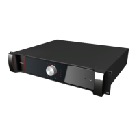
Plixus Engine
Room Equipment
televic
POWER48vDC
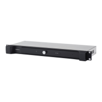
Plixus Power Supply
FLOOR MICROPHONE MUTE
! " # $ % & '
FLOOR MICROPHONE MUTE
! " # $ % & '
FLOOR MICROPHONE MUTE
! " # $ % & '
Figure 1-24 Example of Plixus network with engine only
For a setup where you only need an engine, connect the units directly to the conference ports of the Plixus
engine. Daisy chain the different units in the branch. If your system contains uniCOS units, you need an
external power supply.
Only mix compatible units in one branch. For more information on which units you can combine see "Plixus
component properties" on page50. In this table you can also see the power consumption, which you need
to know how many units you can have in one branch. Use the power calculator tool to validate your
configuration ("Power supply design" on page61).
Configuration With Network Extender
DAISY-CHAIN NETWORK EXTENDERS
When you daisy-chain network extenders, you can have a maximum of 32 network extenders ( eight per
branch and this for the four Plixus conference ports).
INSTAL L ATIO N DIAG RAM 55