ML865G1 HW Design Guide
1VV0301632 Rev. 4 Page 52 of 86 2020-09-23
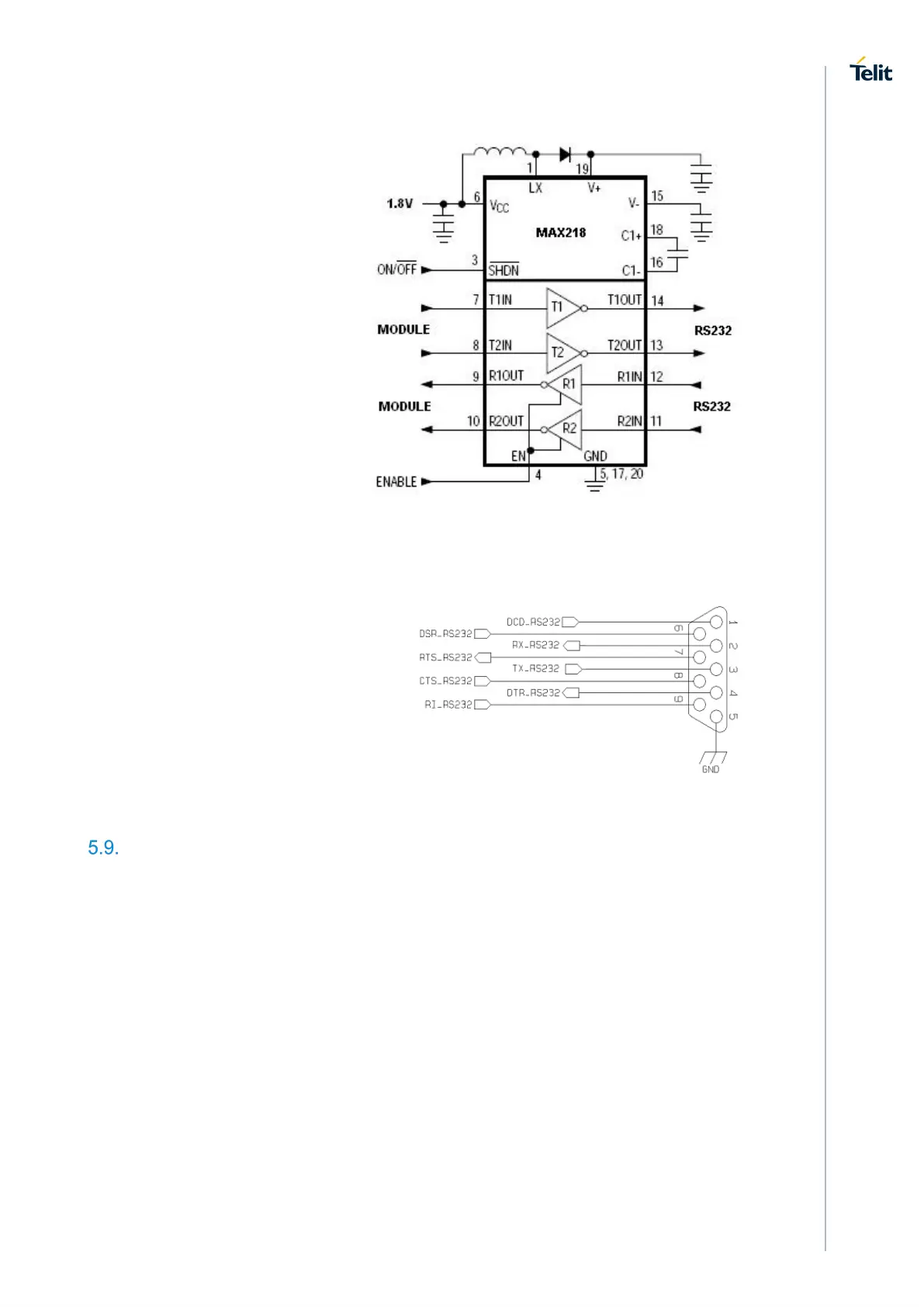
• 3 receivers
An example of RS232 level
adaptation circuitry could be done
using a MAXIM transceiver
(MAX218)
In this case the chipset is capable
to translate directly from 1.8V to
the RS232 levels (Example done
on 4 signals only).
The RS232 serial port lines are usually connected to a DB9 connector with the following
layout:
General purpose I/O
The ML865G1 module is provided by a set of Configurable Digital Input / Output pins
(CMOS 1.8V). Input pads can only be read; they report the digital value (high or low)
present on the pad at the read time. Output pads can only be written or queried and set
the value of the pad output.
An alternate function pad is internally controlled by the ML865G1 firmware and acts
depending on the function implemented.
The following table shows the available GPIO on the ML865G1: