ML865G1 HW Design Guide
1VV0301632 Rev. 4 Page 74 of 86 2020-09-23
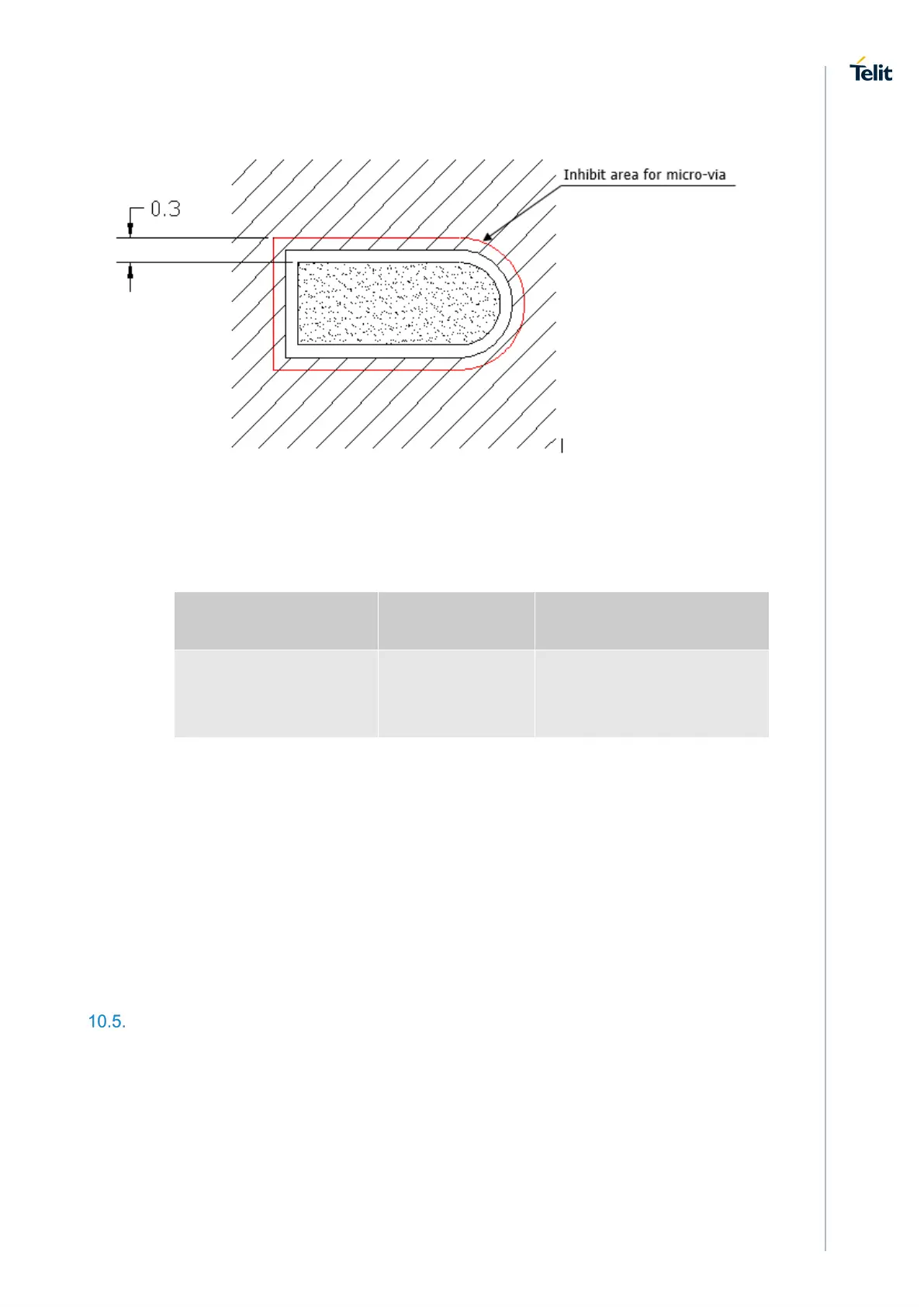
Holes in pad are allowed only for blind holes and not for through holes.
Recommendations for PCB pad surfaces:
Finish Layer thickness
[µm]
Properties
Electro-less Ni /
Immersion Au
3 –7 / 0.03 – 0.15
good solder ability
protection,
high shear force values
The PCB must be able to resist the higher temperatures which are occurring at
the lead-free process. This issue should be discussed with the PCB-supplier.
Generally, the wettability of tin-lead solder paste on the described surface plating
is better compared to lead-free solder paste.
It is not necessary to panel the application PCB, however in that case it is
suggested to use milled contours and predrilled board breakouts; scoring or v-cut
solutions are not recommended.
Stencil
Stencil’s apertures layout can be the same of the recommended footprint (1:1), we
suggest a thickness of stencil foil ≥ 120 µm.