EasyManuals Logo

Telit Wireless Solutions ML865G1 User Manual

Telit Wireless Solutions ML865G1
86 pages
To Next Page IconTo Next Page
To Previous Page IconTo Previous Page
Page #62 background imageLoading...
Page #62 background image
ML865G1 HW Design Guide
1VV0301632 Rev. 4 Page 62 of 86 2020-09-23
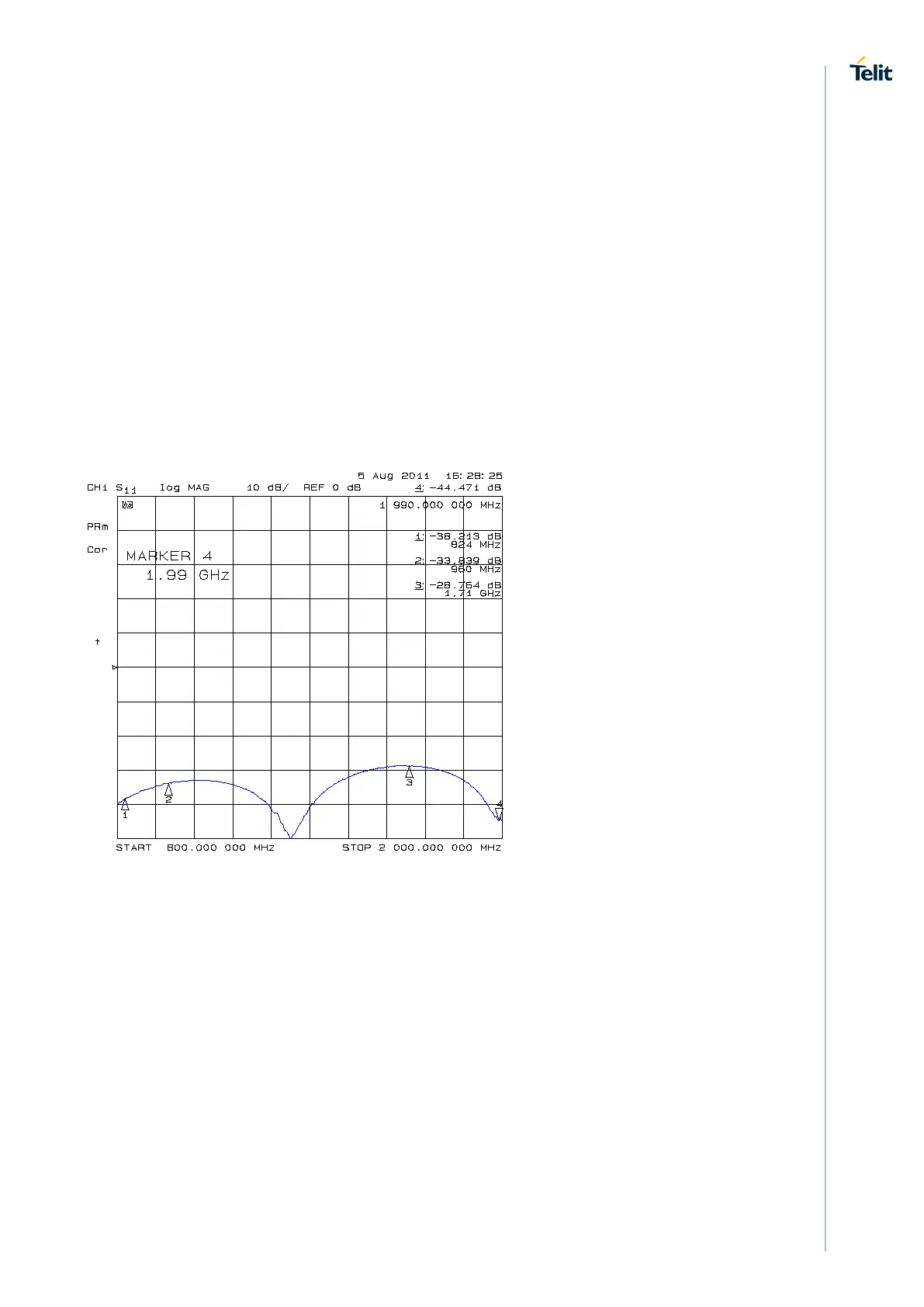
6.4.2.2. Transmission Line Measurements
An HP8753E VNA (Full-2-port calibration) has been used in this measurement session.
A calibrated coaxial cable has been soldered at the pad corresponding to RF output; a
SMA connector has been soldered to the board in order to characterize the losses of the
transmission line including the connector itself. During Return Loss / impedance
measurements, the transmission line has been terminated to 50 Ω load.
Return Loss plot of line under test is shown below:

Table of Contents

Other manuals for Telit Wireless Solutions ML865G1

Questions and Answers:

Question and Answer IconNeed help?

Do you have a question about the Telit Wireless Solutions ML865G1 and is the answer not in the manual?

Telit Wireless Solutions ML865G1 Specifications

General IconGeneral
BrandTelit Wireless Solutions
ModelML865G1
CategoryWireless modules
LanguageEnglish

Related product manuals