NET-PATH Installation and Operation Guide
Page 2-11
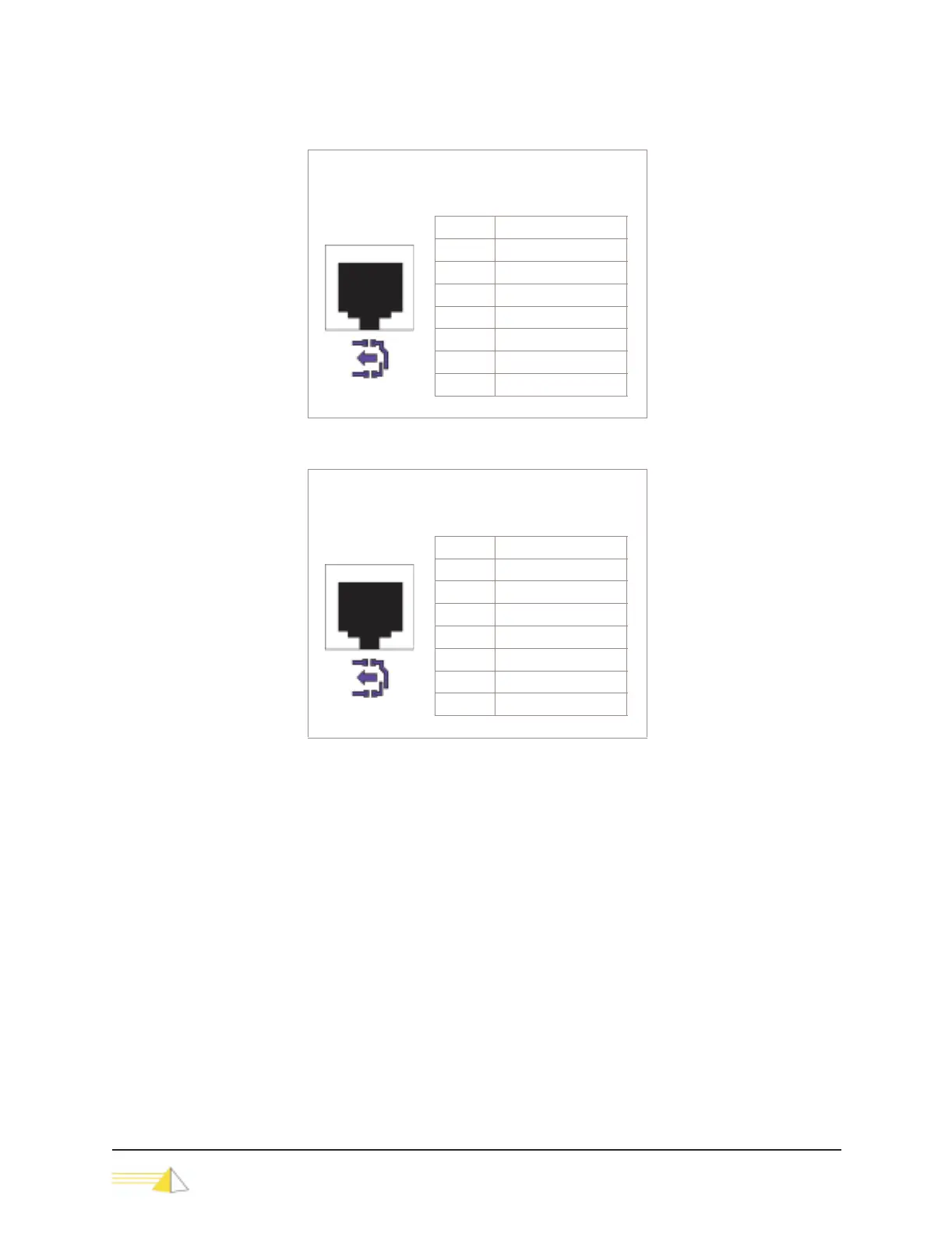
Figure 2-13 RJ45 Wiring Table - Contact Sensors 9 - 12
Figure 2-14 RJ45 Wiring Table - Contact Sensors 13 - 16
NET-PATH eight-port models support contact sensors 1–16.
Output Relays The NET-PATH provides two output control relays configured as Single Pole, Double
Throw (SPDT). The SPDT relay supports normally open or normally closed wiring
configurations. Output relays can be configured to a default state using a combination
of database programming and/or physical wiring. They can be controlled
automatically by the software application or manually through the LCD display
panel. The output control relays are available through an RJ45 connector labeled
Output Relays, which is marked with a yellow symbol.
Contact Sensors 9 - 12
RJ45 Connector
8 Pin Female
Pin # Contact Sensor Inputs
1 Sensor 12+
2Sensor 11+
3 Sensor 10+
4 Sensor 9+
5 Sensor 9 Gnd
6 Sensor 10 Gnd
7Sensor 11 Gnd
8 Sensor 12 Gnd
Contact Sensors 13 - 16
RJ45 Connector
8 Pin Female
Pin # Contact Sensor Inputs
1 Sensor 16+
2 Sensor 15+
3 Sensor 14+
4 Sensor 13+
5 Sensor 13 Gnd
6 Sensor 14 Gnd
7 Sensor 15 Gnd
8 Sensor 16 Gnd