installing disposableschapter 6 6-56-4
2 Using sterile technique, remove the blue cap from the female luer end of
the Shunt Bypass Line and the small top luer cap (white) from the top of
the CDI Shunt Sensor. Attach the CDI Shunt Sensor to the female luer
end of the Bypass Shunt Line.
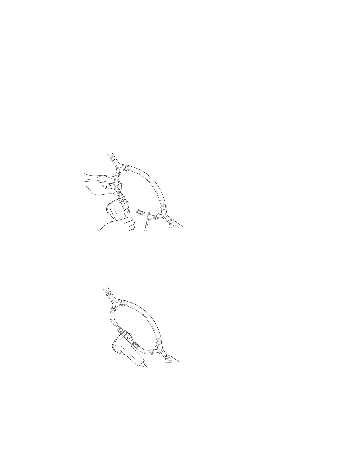
3 Using sterile technique, remove the white cap from the male rotating luer
connector on the Shunt Bypass Line. Remove the filter/sparger assem-
bly (clear) from the CDI Shunt Sensor. Attach the male rotating luer end
of the Shunt Bypass Line onto the CDI Shunt Sensor.
Note: Blood ow can go either direction through the shunt sensor, but the sensor will
t onto the Shunt Bypass Line only one way.
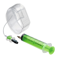
4 Unclamp the Shunt Bypass Lines and start the pump to circulate prime
solution through the shunt sensor. Prime and debubble CDI Shunt
Sensor and the Shunt Bypass Line, inspecting the line and CDI Shunt
Sensor for bubbles. Verify that the cable-head is sufficiently supported
and that the tubing is not kinked.
Note: If the Shunt Bypass Line has been placed in the bypass circuit and the CDI
Shunt Sensor is not going to be used, one of the following steps should be taken:
Remove the Shunt Bypass Line from the circuit, or
Connect the short legs of the Shunt Bypass Line together (female luer connector
to male rotating luer connector).