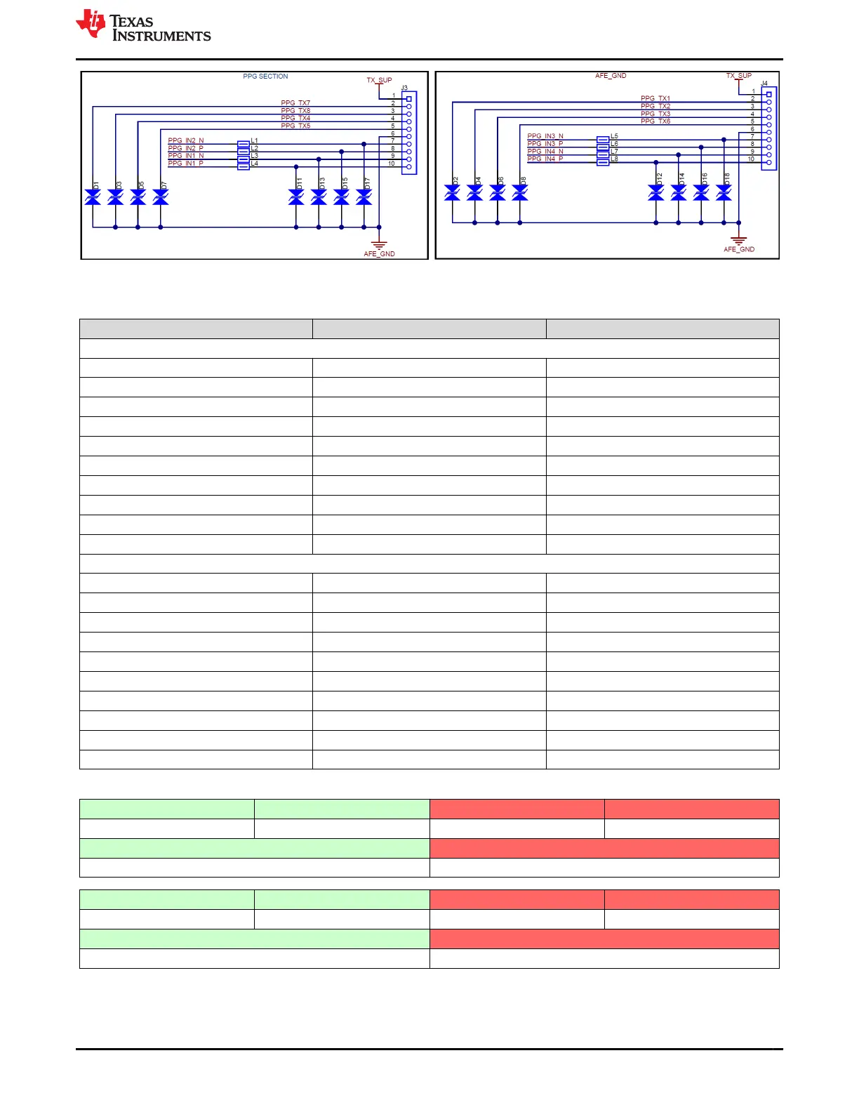
Figure 4-2. 10 pin PPG sensor board interface connector pinout
Table 4-2. PPG Sensor board pinout map
Pin Number AFE Pin Name SFH7072 PIN Description
J3 connector, SFH7072 sensor board 1
1 TX_SUP Power Supply for LEDs
2 TX7 GREEN LED2
3 TX8 RED LED
4 TX4 IR LED
5 TX5 GREEN LED1
6 GND Ground
7 INM2 IR CUT anode
8 INP2 IRCUT cathode
9 INM1 Broadband PD anode
10 INP1 Broadband PD cathode
J4 connector, SFH7072 sensor board 2
1 TX_SUP Power Supply for LEDs
2 TX1 GREEN LED2
3 TX2 RED LED
4 TX3 IR LED
5 TX6 GREEN LED1
6 GND Ground
7 INM3 IR CUT anode
8 INP3 IRCUT cathode
9 INM4 Broadband PD anode
10 INP4 Broadband PD cathode
Table 4-3. PPG Sensor LED, PD connections to the AFE ports
Green LED1 Green LED2 Red LED IR LED
TX5 TX7 TX8 TX4
Green (IR Cut) PD RED/IR (Broadband) PD
PD2 (INP2-INM2) PD1 (INP1-INM1)
Green LED1 Green LED2 Red LED IR LED
TX6 TX1 TX2 TX3
Green (IR Cut) PD RED/IR (Broadband) PD
PD3 (INP3-INM3) PD4 (INP4-INM4)
www.ti.com Connector Interface
SBAU370 – APRIL 2021
Submit Document Feedback
AFE4500 EVM User Guide 21
Copyright © 2021 Texas Instruments Incorporated