Per phase parameters such as PD connection, Rf, Cf, OFFDAC and type of AACM should be independently
configured for both the TIAs.
• Column ‘L’ through column ‘U’ for TIA1
• Column ‘W’ through column ‘AF’ for TIA2
5.1.2 Device Configuration
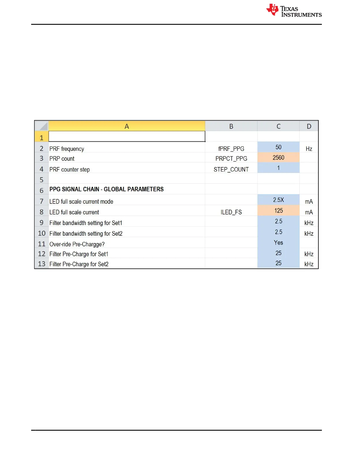
This sheet is used to specify the Global controls for the AFE. This includes the specification of whether the
LDO is enabled or not as well as the mode of clocking (External clock mode using a free-running clock on the
clock input, internal oscillator mode, or Single-shot mode using a Pulse train on the clock input). Fill the rows
in sequence from top to bottom. Fill only the parameters that show up in the Blue boxes. Manually fill each cell
using the drop down boxes (do not cut and paste values across cells). Do not modify the cream-colored boxes.
The light green boxes can be either left blank (to use the default values) or can be filled.
Figure 5-2. PPG global configuration
5.2 ECG-Configuration
Settings related to ECG can be configured in the worksheet called ECG-Configuration. ECG parameters
such as INA Gain, Electrode configuration, Lead detection and saturation detection can be configured in this
worksheet.
AFE4500 Register Generation Excel
www.ti.com
24 AFE4500 EVM User Guide SBAU370 – APRIL 2021
Submit Document Feedback
Copyright © 2021 Texas Instruments Incorporated