EasyManuals Logo

Texas Instruments AFE4500EVM User Manual

Texas Instruments AFE4500EVM
52 pages
To Next Page IconTo Next Page
To Previous Page IconTo Previous Page
Page #22 background image
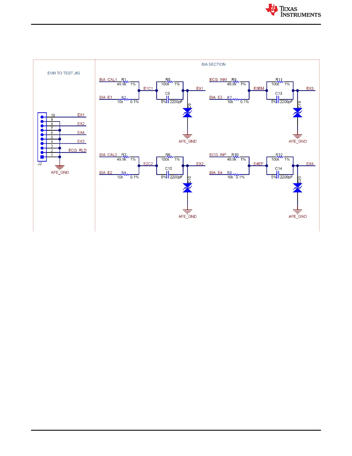
4.3 10-Pin BIA+ECG Connector
Figure 4-3 shows the 10-pin BIA+ECG connector pinout. The BIA and ECG demonstration boards need to be
interface to this connector.
Figure 4-3. 10 pin PPG sensor board interface connector pinout
Connector Interface
www.ti.com
22 AFE4500 EVM User Guide SBAU370 – APRIL 2021
Submit Document Feedback
Copyright © 2021 Texas Instruments Incorporated

Questions and Answers:

Question and Answer IconNeed help?

Do you have a question about the Texas Instruments AFE4500EVM and is the answer not in the manual?

Texas Instruments AFE4500EVM Specifications

General IconGeneral
TypeEvaluation Module
Input Voltage Range3.3V
InterfaceUSB
Part NumberAFE4500EVM
ManufacturerTexas Instruments
Supported DeviceAFE4500
DescriptionEvaluation module for AFE4500, a fully integrated analog front-end for photoplethysmography (PPG) and electrocardiogram (ECG) applications.
FunctionEvaluation and Development

Related product manuals