1.5 Setup the Hardware
Prepare the EVM for signal acquisition as described below
1. Make sure all necessary jumper caps are placed. None of the jumper caps should be modified when EVM is
powered. Table 1-2 shows the EVM Default jumper configuration.
Table 1-2. Default Shunt Positions
SHUNT CONNECTOR
SH-J3 J1[1-2]
SH-J4 J1[3-4]
SH-J5 J1[5-6]
SH-J6 J1[7-8]
SH-J7 J1[9-10]
SH-J8 J1[13-14]
SH-J9 J1[15-16]
SH-J10 J1[17-18]
SH-J11 J1[19-20]
SH-J12 J1[21-22]
SH-J13 J7
SH-J14 J8
SH-J15 J7[2-3]
SH-J16 J11
SH-J17 J10
SH-J18 J1[11-12]
SH-J19 J1[23-24]
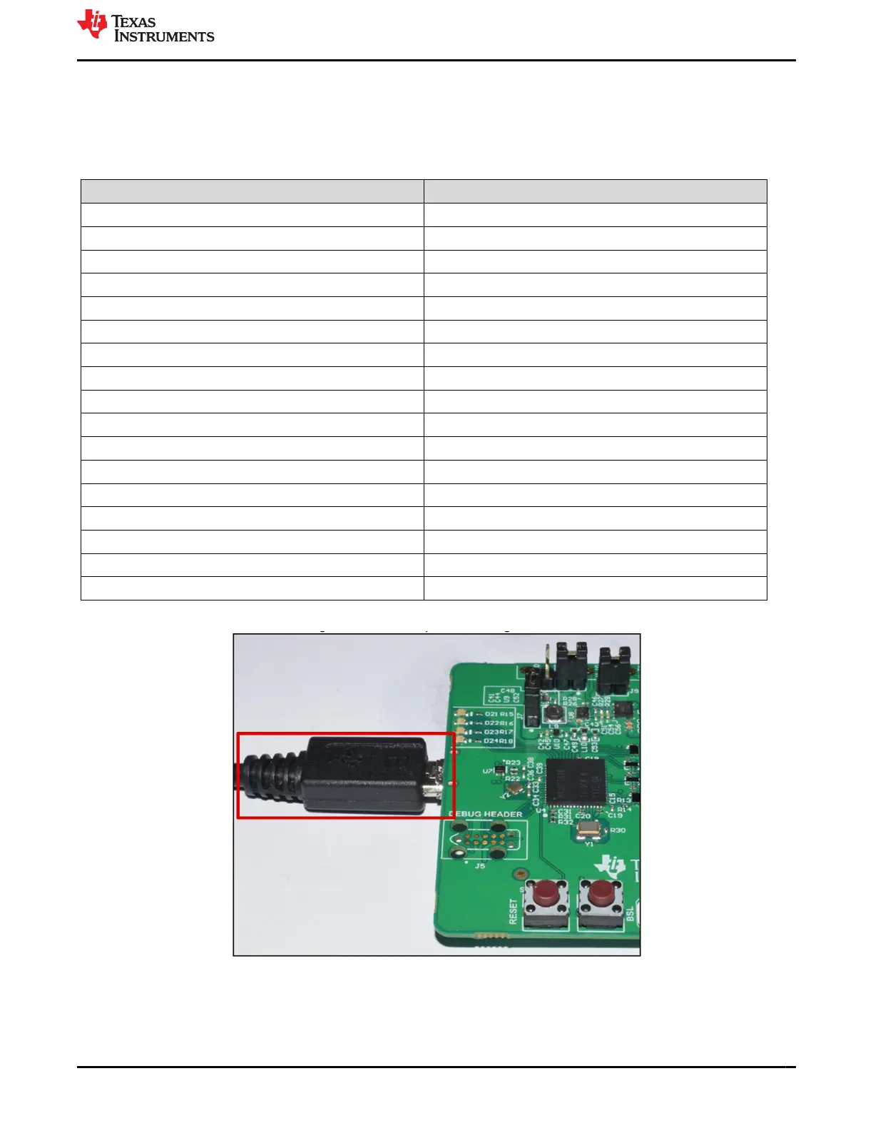
2. Connect the EVM to PC using USB micro cable provided along with the EVM as shown in Figure 1-4.
Figure 1-4. Connecting USB cable to AFE4500EVM
3. Connect the PPG sensor module to the EVM’s J3 connector using 10-pin to 10-pin sensor board extension
cable. Make sure that the sensor module is connected in the correct orientation, that is the pin 1 should line
up with the marking on the cable as shown in Figure 1-5.
www.ti.com
AFE4500 EVM Evaluation
SBAU370 – APRIL 2021
Submit Document Feedback
AFE4500 EVM User Guide 5
Copyright © 2021 Texas Instruments Incorporated