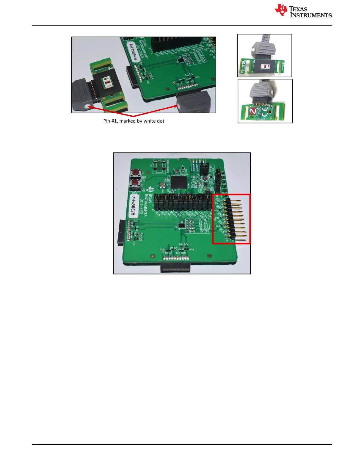
Figure 1-5. Connecting the PPG sensor board to the EVM
4. As shown in Figure 1-6, connect the connector board with ECG connector to the J2 Connector of
AFE4500EVM and the connect the ECG Cables provided to the ECG connectors on the connector board.
Figure 1-6. Connecting the ECG cables to the EVM
5. Place the sensor side of the PPG sensor board on the wrist and tie it snugly. Figure 1-7 shows the sensor
board being held with a Velcro strap. Connect the ECG simulator to EX3, EX4 and RLD of the connector
board.
AFE4500 EVM Evaluation
www.ti.com
6 AFE4500 EVM User Guide SBAU370 – APRIL 2021
Submit Document Feedback
Copyright © 2021 Texas Instruments Incorporated