4 Connector Interface
The following connectors are used for external interface to the AFE4500 Evaluation Module:
• Micro-USB connector
• 10-pin PPG connector
• 10-pin BIA+ECG connector
4.1 Micro-USB Connector
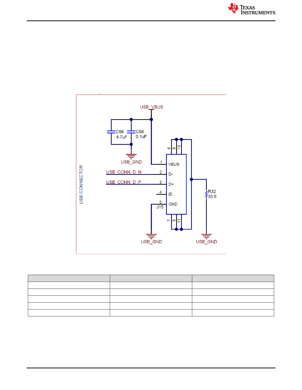
The USB micro connector pin-outs are shown in Figure 4-1. The description of the pin-outs is provided in Table
4-1.
Figure 4-1. USB Micro Connector Pinouts
Table 4-1. USB Micro Connector Pinout Descriptions
Pin Number Pin Name Pin Description
1 VBUS USB power 5 V
2 D– USB DM
3 D+ USB DP
4 ID NC
5 GND GND
4.2 10-Pin PPG Connector
The 10-pin connector pin-outs are shown in Figure 4-2 and Figure 4-3 with description in Table 4-2 . EVM uses
two SFH7072 sensor boards. The connections of the sensor board to the AFE are also listed in Table 4-3
Connector Interface
www.ti.com
20 AFE4500 EVM User Guide SBAU370 – APRIL 2021
Submit Document Feedback
Copyright © 2021 Texas Instruments Incorporated