Sine
Generator
AFE58xxxx TSW1400
Analog Input ADC Data
LVDS
Ch1
TX_TRIG
Sync1(J14)
Anlg In
Sync2(J15)
Trigger Input(J11)
LVDS In
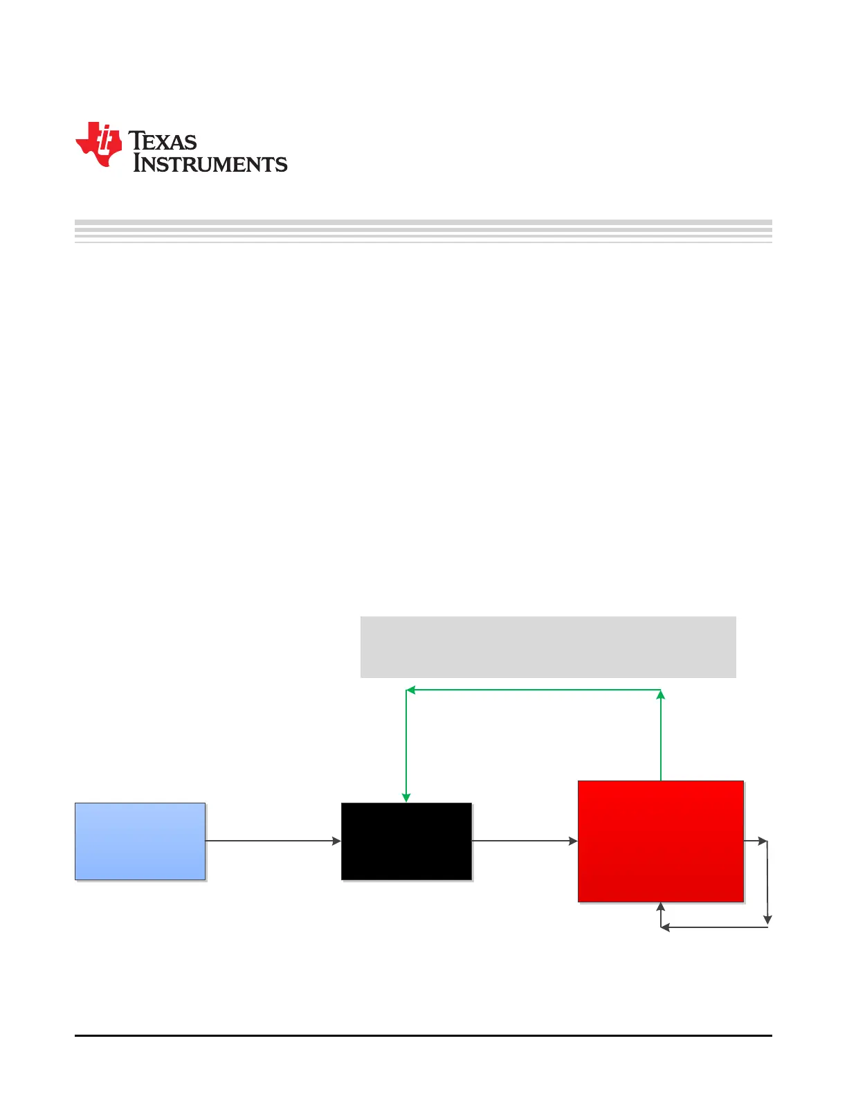
Trigger Configuration 1: Trigger is provided by TSW EVM and can be routed to TX_trig
(if needed) or other equipment via SMA cable. TSW also requires routing a copy of the
trigger back to itself in order to trigger itself. In HSDCPro, µ•šZ^^}(šÁŒdŒ]PPŒ
vo_}‰š]}vµvŒ^dŒ]PPŒK‰š]}v•_
54
SLOU489–August 2017
Submit Documentation Feedback
Copyright © 2017, Texas Instruments Incorporated
Triggering Options
Appendix D
SLOU489–August 2017
Triggering Options
D.1 ADC Synchronization and TX_TRIG
In the analog-front-end, 16 ADCs are being used to convert the 32 inputs. Each ADC converts one odd-
numbered input and one even-numbered input. For example, ADC 1 converts inputs 1 and 2; ADC 2
converts inputs 3 and 4, and so forth. As two inputs need to be processed by each ADC, the inputs are
alternately converted using two sampling circuits within each ADC.
The device has many PLLs and clock dividers that can synchronize the various test patterns generated.
The device has a TX_TRIG input that is used to synchronize the clock dividers inside the device, and this
enables multiple parallel devices to be synchronized as well. This TX_TRIG signal provides the means to
determine when the odd and even signals should be sampled with respect to the rest of the system and its
clock.
Refer to the ADC Synchronization Using TX_TRIG and Input Multiplexer and Sampler sections in the
AFE5832 data sheet (SBAS823) for more information.
D.2 Software Trigger
One method of triggering the TSW EVM, AFE EVM as well as other bench equipment such as function
generators is to generate the trigger from the TSW EVM itself. This requires a feedback loop from the
TSW trigger output to the TSW trigger input using a short SMA cable. Secondly, a second trigger output
from the TSW board can be routed to the AFE EVM, if needed, or to external bench equipment such as a
function generator. See the TSW or HSDC Pro manual for more information.
Figure 65. HSDC Pro Trigger Configuration for SW