www.ti.com
Using the EVM in CW Mode
17
SLOU489–August 2017
Submit Documentation Feedback
Copyright © 2017, Texas Instruments Incorporated
AFE5832 32-Channel Analog Front-End Evaluation Module (EVM Rev. A)
6 Using the EVM in CW Mode
Demonstrating the CW mixer in the AFE is done by following these steps:
1. In the AFE5832 GUI, reset and initialize the device by referring to Figure 10 and Figure 11. Remember
to connect a –5-V and a 5-V source to the device.
2. Connect a sine wave generator to any SMA channel. Set the frequency to 1.963125 MHz and the
amplitude to –23 dBm.
3. Provide a 125-MHz, +10-dBm clock input to J56 of the AFE EVM (LMK external clock). Refer to
Section C.1.3 for jumper configurations.
4. Turn Switch 4 contained in S5 on the AFE EVM to 'on'. The red LED, D8 should not light up. For more
information on the CPLD, refer to Section C.1.4.
5. Connect two cables to an oscilloscope with timebase of 40 µs and 500 mV / div. Input resistance
should be 1 MΩ on each scope channel. DC couple the oscilloscope.
6. Connect those two cables to SMAs, J66 and J68 on the AFE EVM.
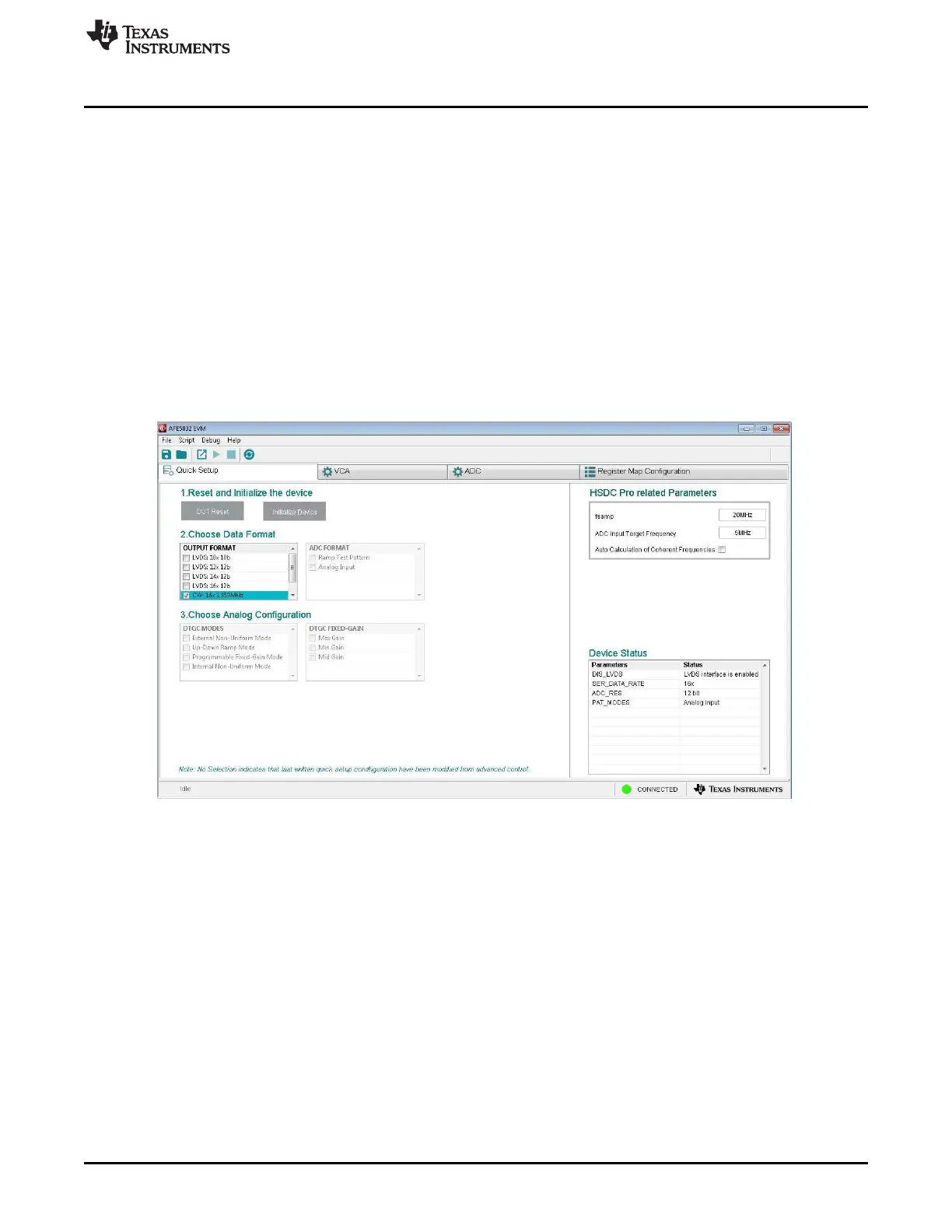
7. Choose the following data format on the AFE5832 EVM GUI:
Figure 20. CW Mode Preset
8. Trigger the oscilloscope on either channel.
9. The oscilloscope displays the frequency I and Q signals at 10 kHz as shown in Figure 21. The
amplitude should be around 1.5 Vpp ±300 mVpp, though this amplitude may change. The frequency
should be 10 kHz and the I and Q signals should be 90 degrees out of phase.