www.ti.com
EVM Headers, Test Points, and Configuration
53
SLOU489–August 2017
Submit Documentation Feedback
Copyright © 2017, Texas Instruments Incorporated
Hardware Configuration
Configuration 3: To use the differential outputs from the LMK04821 as the clock source for the AFE,
connect shunt jumpers for configuration 3 (as seen in Figure 63). The clock signal can be generated either
from the 40-MHz onboard crystal (Y1), the 125-MHz onboard crystal (Y2), or an external clock generator.
To use the 125-MHz onboard crystal, connect the J54 jumper as indicated by option 2 (Figure 63). To use
the 40-MHz onboard crystal, connect the J54 jumper as indicated by option 1 (Figure 63). For an external
source, connect an external clock generator to J56, and set the clock source to 160 MHz, and +13-dBm
amplitude. For an external source, leave the J54 jumper as in configuration 2.
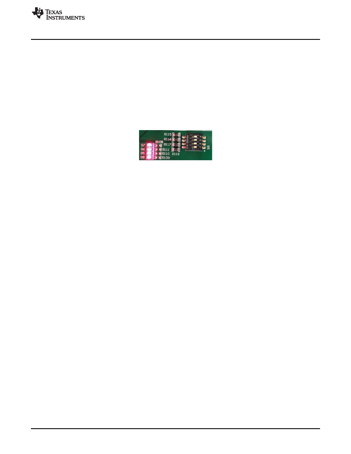
C.1.4 Complex Programmable Logic Device (CPLD)
The AFE5832 board has a Xilinx™ CPLD, designated by U21 on the schematic. This CPLD is controlled
by four switches contained in S5 on the board. When all of these switches are in the ‘off’ position, LEDs
D5 – D8 should light up on the board as shown in Figure 64.
Figure 64. CPLD Switches and LEDs
The following describes the function of each of the four switches contained in S5:
Switch 1: In the ‘off’ position, this switch turns on the TGC signals. In the ‘on’ position, these signals are
turned off.
Switch 2: This switch determines whether the CPLD outputs signals for Up-Down Ramp Mode or External
Non-Uniform Mode when running a DTGC test. In the ‘off’ position, the CPLD outputs for Up-Down Ramp
Mode, and in the ‘on’ position, the CPLD outputs for External Non-Uniform Mode.
Switch 3: This switch controls the distance between two consecutive TGC_SLOPE pulses for Up-Down
Ramp Mode.
Switch 4: This switch controls TX_TRIG. The TX_TRIG pulse resets the phase of the test pattern
generator, the odd and even sampling phase selection, and the phase of the frame clock. This phase
reset can corrupt the ADC data because the clock dividers will no longer be synchronized. In the ‘off’
position, Switch 4 turns on the TX_TRIG pulse, and in the ‘on’ position, the TX_TRIG pulse is turned off.
The switches controlling the CPLD must be manipulated for some of the modes outlined in this user guide.
Switch 4 is the most important to pay attention to as it controls whether or not the phase is reset. As a
summary, the modes with their corresponding Switch 4 settings are outlined in the following list:
• LVDS Capture – Switch 4 off and LED D8 on
• DTGC Mode Test – Switch 4 off and LED D8 on
• CW Mode Test – Switch 4 on and LED D8 off