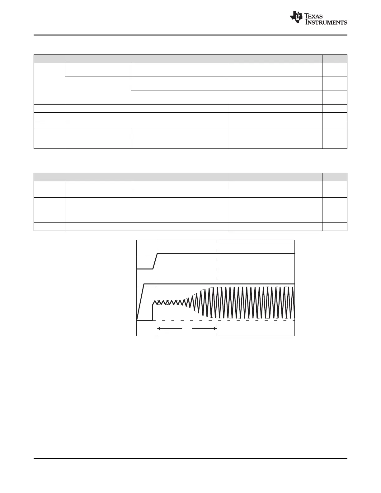
VDDS_RTC
RTC_XTALOUT
t
sX
CAP_VDD_RTC (min.)
Time
Voltage
VSS_RTC
VDDS_RTC (min.)
VSS_RTC
CAP_VDD_RTC
AM3359, AM3358, AM3357, AM3356, AM3354, AM3352
SPRS717H –OCTOBER 2011–REVISED MAY 2015
www.ti.com
Table 6-5. OSC1 Crystal Circuit Requirements
NAME DESCRIPTION MIN TYP MAX UNIT
ƒ
xtal
Crystal parallel resonance Fundamental mode oscillation only 32.768 kHz
frequency
Crystal frequency stability Maximum RTC error = 10.512 minutes –20.0 20.0 ppm
and tolerance
(1)
per year
Maximum RTC error = 26.28 minutes per –50.0 50.0 ppm
year
C
C1
C
1
capacitance 12.0 24.0 pF
C
C2
C
2
capacitance 12.0 24.0 pF
C
shunt
Shunt capacitance 1.5 pF
ESR Crystal effective series ƒ
xtal
= 32.768 kHz, oscillator has nominal 80 kΩ
resistance negative resistance of 725 kΩ and worst-
case negative resistance of 250 kΩ
(1) Initial accuracy, temperature drift, and aging effects should be combined when evaluating a reference clock for this requirement.
Table 6-6. OSC1 Crystal Circuit Characteristics
NAME DESCRIPTION MIN TYP MAX UNIT
C
pkg
Shunt capacitance of ZCE package 0.17 pF
package
ZCZ package 0.01 pF
P
xtal
The actual values of the ESR, ƒ
xtal
, and C
L
should be used to yield a P
xtal
= 0.5 ESR (2 π ƒ
xtal
C
L
typical crystal power dissipation value. Using the maximum values VDDS_RTC)
2
specified for ESR, ƒ
xtal
, and C
L
parameters yields a maximum power
dissipation value.
t
sX
Start-up time 2 s
Figure 6-14. OSC1 Start-up Time
112 Power and Clocking Copyright © 2011–2015, Texas Instruments Incorporated
Submit Documentation Feedback
Product Folder Links: AM3359 AM3358 AM3357 AM3356 AM3354 AM3352
 Loading...