MMC[x]_CLK (Output)
1
2
MMC[x]_CMD (Input)
MMC[x]_DAT[7:0] (Inputs)
3
4
AM3359, AM3358, AM3357, AM3356, AM3354, AM3352
www.ti.com
SPRS717H –OCTOBER 2011–REVISED MAY 2015
7.13 Multimedia Card (MMC) Interface
For more information, see the Multimedia Card (MMC) section of the AM335x Sitara Processors Technical
Reference Manual (SPRUH73).
7.13.1 MMC Electrical Data and Timing
Table 7-86. MMC Timing Conditions
PARAMETER MIN TYP MAX UNIT
Input Conditions
t
r
Input signal rise time 1 5 ns
t
f
Input signal fall time 1 5 ns
Output Condition
C
load
Output load capacitance 3 30 pF
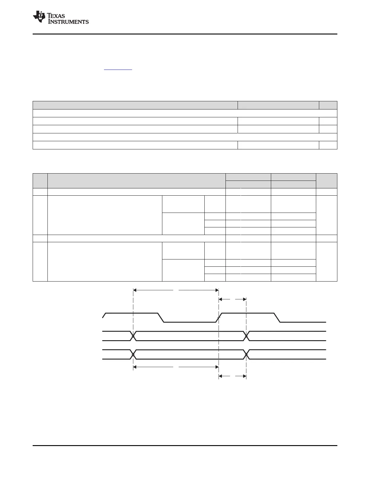
Table 7-87. Timing Requirements for MMC[x]_CMD and MMC[x]_DAT[7:0]
(see Figure 7-92)
1.8-V MODE 3.3-V MODE
NO. UNIT
MIN TYP MAX MIN TYP MAX
1 t
su(CMDV-CLKH)
Setup time, MMC_CMD valid before MMC_CLK rising clock edge 4.1 4.1 ns
Industrial extended
temperature MMC0-2 3.76 3.76
(-40°C to 125°C)
Hold time, MMC_CMD valid after
2 t
h(CLKH-CMDV)
ns
MMC0 3.76 2.52
MMC_CLK rising clock edge
All other
MMC1 3.76 3.03
temperature ranges
MMC2 3.76 3.0
3 t
su(DATV-CLKH)
Setup time, MMC_DATx valid before MMC_CLK rising clock edge 4.1 4.1 ns
Industrial extended
temperature MMC0-2 3.76 3.76
(-40°C to 125°C)
Hold time, MMC_DATx valid after
4 t
h(CLKH-DATV)
ns
MMC0 3.76 2.52
MMC_CLK rising clock edge
All other
MMC1 3.76 3.03
temperature ranges
MMC2 3.76 3.0
Figure 7-92. MMC[x]_CMD and MMC[x]_DAT[7:0] Input Timing
Copyright © 2011–2015, Texas Instruments Incorporated Peripheral Information and Timings 221
Submit Documentation Feedback
Product Folder Links: AM3359 AM3358 AM3357 AM3356 AM3354 AM3352
 Loading...