www.ti.com
BP-ADS7128 EVM Initial Setup
13
SBAU331–May 2019
Submit Documentation Feedback
Copyright © 2019, Texas Instruments Incorporated
BP-ADS7128 BoosterPack™ Plug-In Module
3.3.2.2 Channel Configuration
This page sets channel-specific configurations, and consist of two tabs:
• Input channels tab: All selected input channels, analog or digital, can be configured
• Output channels tab: The selected digital output channels can be configured
For example, the first three channels were previously selected in the Channel Selection page as an
analog input, digital input, and digital output, respectively. The Channel Configuration page then
automatically updates to reflect the selected channel options.
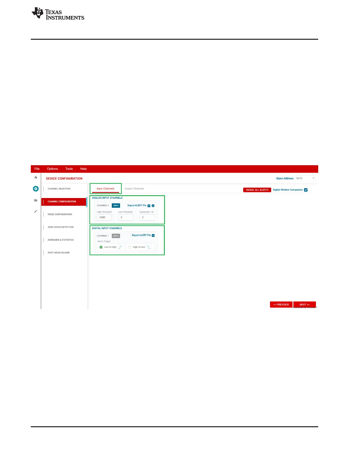
3.3.2.2.1 Input Channels
Continuing with the example, both analog and digital inputs are displayed, as shown in Figure 12, in the
Input Channels tab. Analog channels are listed on top, digital channels are listed below. The available
configuration options are displayed for each type of input.
Any analog input channel can be selected to trigger the ALERT pin when the set high or low threshold
code entered is crossed. Hysteresis can also be configured.
Any digital input channel can be selected to trigger the ALERT pin when the selected state change occurs.
Figure 12. Channel Configuration Page, Input Channel Tab

 Loading...

