BP-ADS7128 EVM Initial Setup
www.ti.com
14
SBAU331–May 2019
Submit Documentation Feedback
Copyright © 2019, Texas Instruments Incorporated
BP-ADS7128 BoosterPack™ Plug-In Module
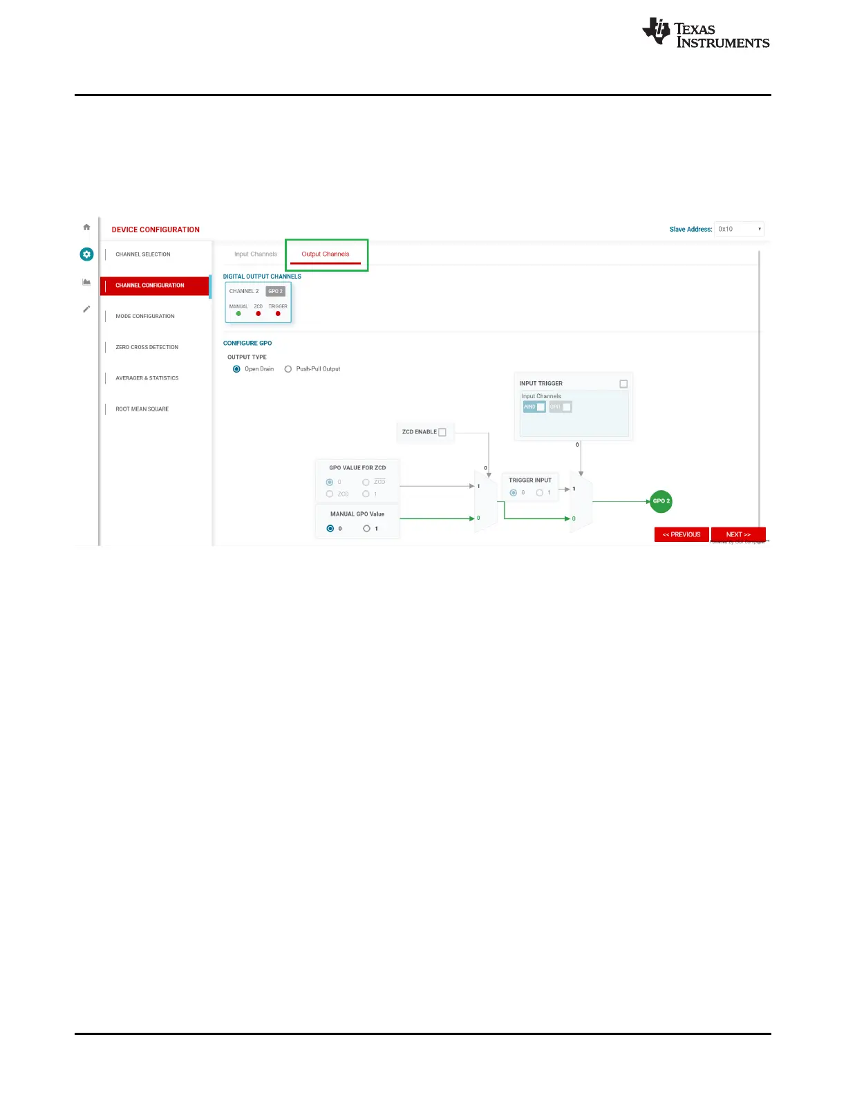
3.3.2.2.2 Output Channels
The output channels tab also auto-updates to display the selected digital output channels in the Channel
Selection page. In this example, only channel 2 was selected as a digital output. In this tab, the digital
output channels can be selected as open-drain (default) or changed to push-pull. Figure 13 shows the
zero-cross detection (ZCD) and trigger logic. This tab visually represents the logic within the device, and
allows the user to enable ZCD, and select the input channels as a trigger.
Figure 13. Channel Configuration Page, Output Channels Tab
3.3.2.2.3 Sampling Mode Configuration
The ADS7128 can operate in three sampling modes. The mode configuration tab (Figure 14) allows the
user to select the device mode of operation.
The ADS7128 device has the following sampling modes:
• Manual Mode: Allows the external host processor to directly request and control when the data are
sampled. The host provides I
2
C frames to control conversions and the captured data are returned over
the I
2
C bus after each conversion.
• Auto-Sequence Mode: The host can configure the device to scan through the enabled analog input
channels. The host must provide continuous clocks (SCL) to the device to scan through the channels
and to read the data from the device. The mux automatically switches through the predetermined
channel sequence, and the data conversion results are sent through the data bus.
• Autonomous Mode: After receiving the first start of conversion pulse from the host, the ADS7128
device then generates the subsequent start of conversion signals autonomously. The device features
an internal oscillator to generate the start of ADC conversion pulses without the host controlling the
conversions. Output data are not returned over the digital bus; only a signal on the ALERT pin is
generated when an input signal crosses the programmable high or low threshold values.
The device powers up in manual mode and can be configured into any of the functional modes by writing
the configuration registers for the desired mode.

 Loading...

