www.ti.com
BP-ADS7128 EVM Initial Setup
23
SBAU331–May 2019
Submit Documentation Feedback
Copyright © 2019, Texas Instruments Incorporated
BP-ADS7128 BoosterPack™ Plug-In Module
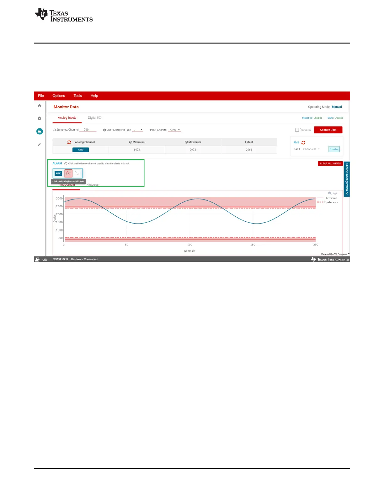
3.3.5.1.3 Alarm
As shown in Figure 24, if an analog input signal crosses the configured thresholds, then an alarm is
triggered, as demonstrated in the analog inputs page within the data capture tab. This page provides an
ALARM section where the corresponding image to the threshold crossed, high or low, turns red when
triggered. The alarm can be cleared by clicking on the red icon.
Figure 24. Alarm Triggered
 Loading...


