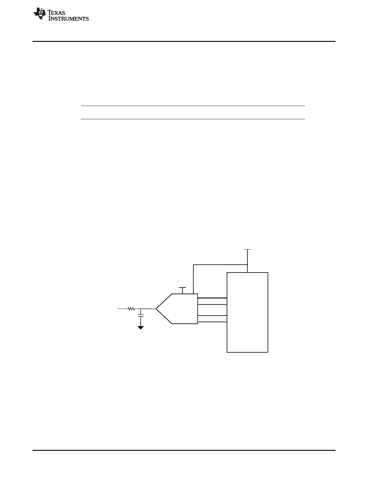
ADS7128
SCL
SDA
ADDR
ALERT
Host MCU
3.3V
AVDD
DVDD
160 …F
10 K
GND
AINx/
GPIOx
www.ti.com
Introduction
3
SBAU331–May 2019
Submit Documentation Feedback
Copyright © 2019, Texas Instruments Incorporated
BP-ADS7128 BoosterPack™ Plug-In Module
1 Introduction
The ADS7128 BoosterPack™ is a fully-assembled evaluation platform designed to highlight the ADS7128
features and various modes of operations that make this device suitable for ultra-low-power, small-size
sensor monitor applications.
The accompanying MSP432E401Y LaunchPad™ development kit (MSP-EXP432E401Y) is used as a
USB-to-PC GUI communication bridge. This kit also serves as an example implementation of a master
microcontroller (MCU) to communicate with the ADS7128 through an I
2
C interface.
NOTE: The BP-ADS7128 requires an external master controller to evaluate the ADS7128.
The MSP-EXP432E401Y is controlled by commands received from the ADS7128 GUI, and returns data to
the GUI for display and analysis. If the MSP-EXP432E401Y is not used, the BoosterPack™ plug-in
module format of the BP-ADS7128 board allows for an alternative external host to communicate with the
ADS7128.
The BP-ADS7128 incorporates all required circuitry and components with the following features:
• ADS7128 low-power, ultra-small, eight-channel sensor monitor with I
2
C interface and alert output
• External power-supply connection available to provide 3.3 V to power the ADS7128 DVDD supply
instead of the universal serial bus (USB) power from the MSP432E401Y LaunchPad™
• Optional adjustable linear regulator, TI’s TPS78001, to generate stable output voltage to power the
ADS7128 AVDD and DVDD pins when using the 5-V USB power from the MSP432E401Y
LaunchPad™
• I
2
C interface for communication and configuration of modes available on the ADS7128
Figure 1 shows the ADS7128EVM architecture, identifying the key components and blocks previously
listed.
Figure 1. ADS7128EVM Block Diagram

 Loading...

