Configuring the GPIO
www.ti.com
90
SLUUBD3D–September 2015–Revised September 2018
Submit Documentation Feedback
Copyright © 2015–2018, Texas Instruments Incorporated
Host Controlled GPIO
GPIO B (Bit 7): GPIO B
1 = If enabled as output, high
0 = If enabled as output, low
GPIO A (Bit 6): GPIO A
1 = If enabled as output, high
0 = If enabled as output, low
LED5 (Bit 5): GPIO 5
1 = If enabled as output, high
0 = If enabled as output, low
LED4 (Bit 4): GPIO 4
1 = If enabled as output, high
0 = If enabled as output, low
LED3 (Bit 3): GPIO 3
1 = If enabled as output, high
0 = If enabled as output, low
LED2 (Bit 2): GPIO 2
1 = If enabled as output, high
0 = If enabled as output, low
LED1 (Bit 1): GPIO 1
1 = If enabled as output, high
0 = If enabled as output, low
RSVD (Bit 0): Reserved
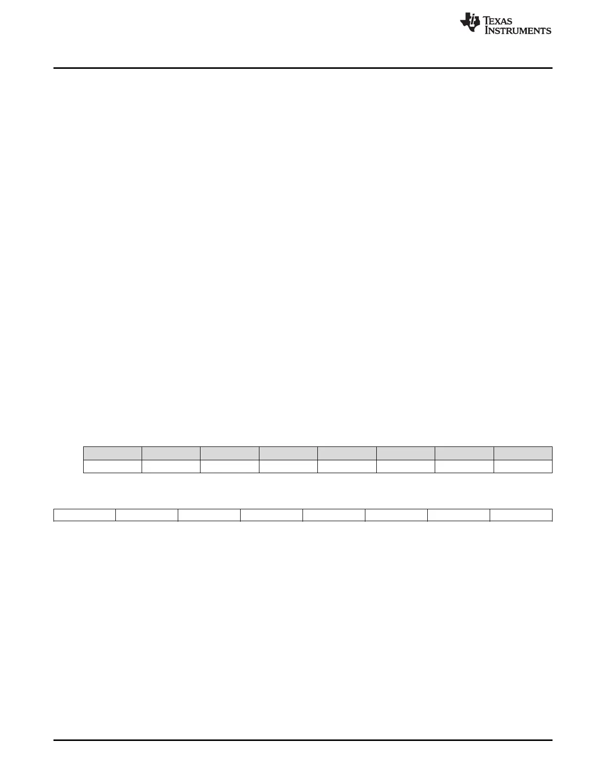
Table 14-4. Host Controlled GPIO Type Configuration
Class Subclass Name Format Min Max Default Unit
GPIO GPIO Config GPIO Type Hex 0x00 0xFE 0xC0 —
7 6 5 4 3 2 1 0
GPIO B GPIO A LED5 LED4 LED3 LED2 LED1 RSVD
GPIO B (Bit 7): GPIO B
1 = Open Drain
0 = 3-mA Current Sink
GPIO A (Bit 6): GPIO A
1 = Open Drain
0 = 3-mA Current Sink
LED5 (Bit 5): GPIO 5
1 = Open Drain
0 = 3-mA Current Sink
LED4 (Bit 4): GPIO 4
1 = Open Drain
0 = 3-mA Current Sink
LED3 (Bit 3): GPIO 3
 Loading...