Hardware
www.ti.com
12
SLAU680–May 2018
Submit Documentation Feedback
Copyright © 2018, Texas Instruments Incorporated
MSP430FR2355 LaunchPad™ Development Kit (MSP
‑
EXP430FR2355)
2.3 Power
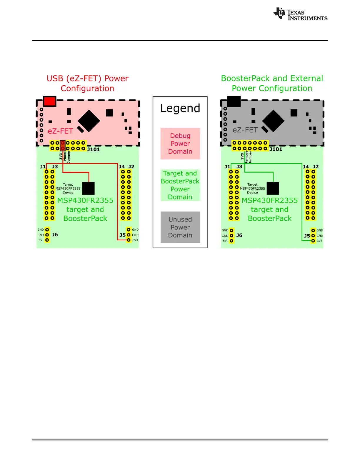
The board accommodates various powering methods, including through the onboard eZ-FET as well as
external or BoosterPack plug-in module power (see Figure 8).
Figure 8. MSP-EXP430FR2355 Power Block Diagram
2.3.1 eZ-FET USB Power
The most common power-supply scenario is from USB through the eZ-FET debugger. This provides 5-V
power from the USB and also regulates this power rail to 3.3 V for eZ-FET operation and 3.3 V to the
target side of the LaunchPad development kit. Power from the eZ-FET is controlled by jumper J101. For
3.3 V, make sure that a jumper is connected across the J101 3V3 terminal.
2.3.2 BoosterPack Plug-in Module and External Power Supply
Header J5 is present on the board to supply external power directly. It is important to comply with the
device voltage operation specifications when supplying external power. The MSP430FR2355 has an
operating range of 1.8 V to 3.6 V. More information can be found in the MSP430FR2355 Mixed-Signal
Microcontroller data sheet.
2.4 Measure Current Draw of the MSP430 MCU
To measure the current draw of the MSP430FR2355 MCU using a multimeter, use the 3V3 jumper on the
J101 jumper isolation block. The current measured includes the target device and any current drawn
through the BoosterPack plug-in module headers.
To measure ultra-low power, follow these steps:
• Remove the 3V3 jumper in the J101 isolation block, and attach an ammeter across this jumper.
• Consider the effect that the backchannel UART and any circuitry attached to the MSP430FR2355 may
have on current draw. Consider disconnecting these at the isolation jumper block, or at least consider
their current sinking and sourcing capability in the final measurement.