www.ti.com
Software Examples
17
SLAU680–May 2018
Submit Documentation Feedback
Copyright © 2018, Texas Instruments Incorporated
MSP430FR2355 LaunchPad™ Development Kit (MSP
‑
EXP430FR2355)
3.1.3 Light Sensor Mode
The Light Sensor mode uses the SAC0 and SAC2 pair, two Timer_B modules, and the ADC of the
MSP430FR2355 MCU, combined with the on-board photodiode and LEDs of the LaunchPad development
kit, to implement a simple light sensing application. It configures SAC2 as a generic op-amp and, together
with R3 and C6, implements a transimpedance amplifier to convert the photodiode current to a voltage. To
measure this voltage with the device’s ADC, the output voltage of SAC2 is then fed through SAC0
(configured as a buffer), whose output is connected internally to the ADC.
When the Out-of-Box demo is first programmed onto the LaunchPad development kit, a default ADC
threshold is set to approximately half of the full brightness detection range of D1. If the ADC measurement
is below this brightness threshold, the red LED1 illuminates, and if the ADC measurement is above the
default threshold, the green LED2 illuminates corresponding to the intensity of the ambient light. To
recalibrate the threshold to the ADC value measured from the ambient light, press S1. The user can
influence the amount of light reaching the photodiode by using a flashlight or covering the photodiode
observing the changes in the LED brightness.
3.1.4 Function Generator Mode
In the Function Generator mode, an input signal (sourced internally or externally) is fed into the SAC1
configured in the Programmable Gain Amplifier (PGA) mode to be manipulated and captured with the
internal ADC. The LaunchPad kit repeatedly measures and transfers this data to the PC through UART.
When the Out-of-Box demo is first programmed onto the LaunchPad development kit, the Function
Generator mode is initially configured to generate a 1-Hz sine wave at 0.8-V amplitude using the SAC3
DAC, and the sine wave is fed into SAC1 configured in the inverting PGA mode with a gain of 1. When
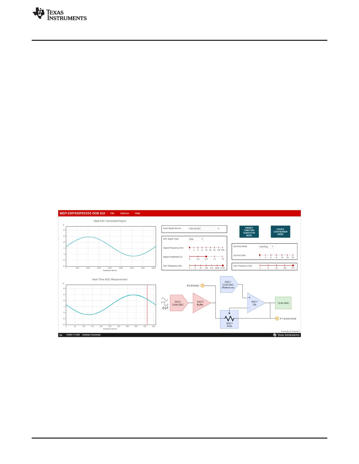
visualized in the OOB GUI, you should see an inverted sine wave as shown in Figure 11.
Figure 11. Default Waveform of the Function Generator Mode
Using the GUI, the input signal source can be selected between the internal 12-bit DAC (SAC3) and an
external signal source. When the “Internal DAC” is selected as the input signal source, the GUI can be
used to generate different types of signals (sinusoidal, square, or sawtooth) of various frequencies and
amplitudes. The SAC1 PGA inverting or noninverting gain can be used to manipulate the generated signal
of the SAC3 DAC, and the output waveform is captured with the internal ADC connection and displayed
on the cloud GUI.