Software Examples
www.ti.com
16
SLAU680–May 2018
Submit Documentation Feedback
Copyright © 2018, Texas Instruments Incorporated
MSP430FR2355 LaunchPad™ Development Kit (MSP
‑
EXP430FR2355)
To use any of the software examples with the LaunchPad development kit, you must have an integrated
development environment (IDE) that supports the MSP430FR2355 device (see Table 5).
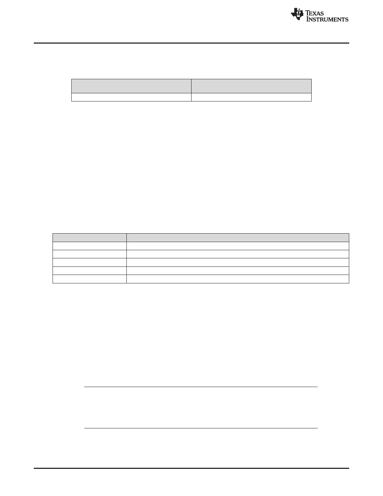
Table 5. IDE Minimum Requirements for MSP-EXP430FR2355
Code Composer Studio IDE
IAR Embedded Workbench for Texas
Instruments MSP430 IDE
v8.0 or later v7.12.1 or later
For more details on how to get started quickly and where to download the latest CCS and IAR IDEs, see
Section 4.
3.1 Out-of-Box Software Example
This section describes the functionality and structure of the Out-of-Box software that is preloaded in the
EVM.
The Out-of-Box Experience (OOBE) of the MSP-EXP430FR2355 LaunchPad development kit
demonstrates how to set up the integrated SAC and use it to condition an analog output so that it can be
properly sampled by the ADC converter on the MCU.
3.1.1 Source File Structure
The project is split into multiple files (see Table 6). This makes it easier to navigate and reuse parts of it
for other projects.
Table 6. Source File and Folders
Name Description
main.c Out-of-Box demo main function
lightsensor.c Contains functions for the Light Sensor mode
functiongenerator.c Contains functions for the Function Generator mode
Library: driverlib Device driver library
Library: jsmn Minimalistic third-party library for parsing JSON formatted strings
3.1.2 Overview
Upon powering up the Out-of-Box demo, the board enters the Light Sensor mode where LED1 or LED2
brightens/dims based on the intensity of the ambient light hitting the on-board photodiode. By pressing
button S2, the board enters the Function Generator mode where an input signal (sourced internally or
externally) is fed into a SAC configured in PGA mode, and the final output waveform is captured with the
internal ADC. At any time, press S2 to switch between the Light Sensor mode and Function Generator
mode.
When the demo is in Function Generator mode, an online cloud GUI (MSP-EXP430FR2355 OOB GUI)
can be used with the development kit to control the input signal source and visualize the real-time ADC
measurement. In addition to S2, the GUI provides buttons that can also be used to switch between
modes.
NOTE: The MSP430FR2355 microcontroller is equipped with four on-chip Smart Analog Combos
(SAC), which come in pairs of two, SAC0 with SAC2 and SAC1 with SAC3. Each pair of
SACs is interconnected, where the output of one SAC can be fed into the input of its paired
SAC. The Out-of-Box demonstrates these interconnections and uses one SAC pair in the
Light Sensor mode and the second SAC pair in the Function Generator mode.