8
Note: Some part features have been hidden from view for visual clarity.
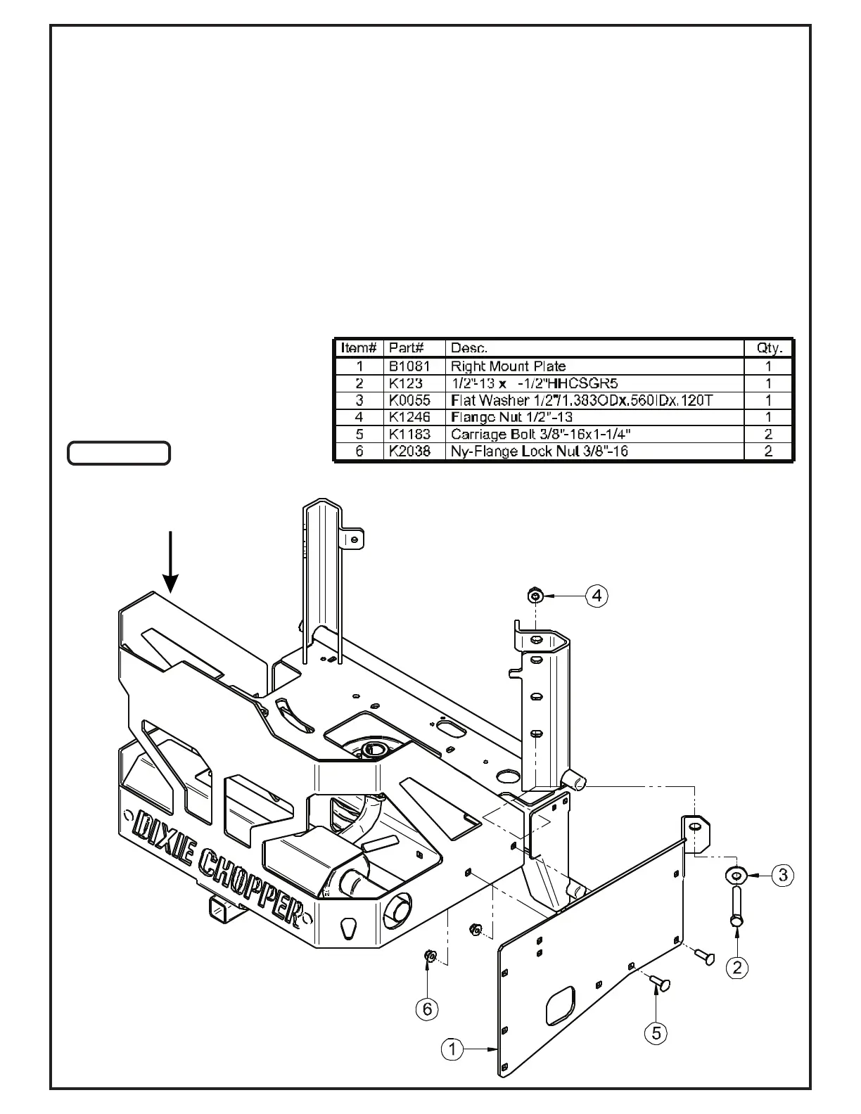
Leave the (2) 3/8”-16 x 1-1/4” Carriage Bolt and (2) 3/8”-16 Ny-Flange Lock Nuts relatively loose for the installation
of the PTO Mount Arm.
Before installing the Right Mount Plate (Item #1), remove the hardware fastening the lower right side of the
mower’s rear bumper to reveal (2) bolt holes. Then remove the hardware from the lower bolt hole of the right side of
the ROPS to reveal (1) bolt hole.
Next, align the bottom (2) right bolt hole of the Right Mount Plate to the ones on the lower left side of the mower’s
rear bumper and align the top right bolt hole of the Right Mount Plate to the one on the ROPS. Secure the Right
Mount Plate to the mower by using (1) 1/2”-13 x 1-1/2” Hex Bolt (Item # 2), (1) 1/2” Flat Washer (Item #3), (1) 1/2”-
13 Flange Nut (Item #4), (2) 3/8”-16 x 1-1/4” Carriage Bolts (Item #5) and (2) 3/8-16” Ny-Flange Lock Nuts (Item
#6). Refer to Figure A.
Right Mount Plate Installation
3
1
Figure A
Rear
Bumper