21
Attach the Positive Lead from the Wiring Harness (P#A2144)
connected to the Metri-Pack 2 Way Connector (P#P0280) to the
PTO Switch (P#J2001) by connecting the Female Disconnector
(P# P0106) from the Positive Lead to the Switch Terminal (A) on
the Switch. Refer to Figure B on the next page.
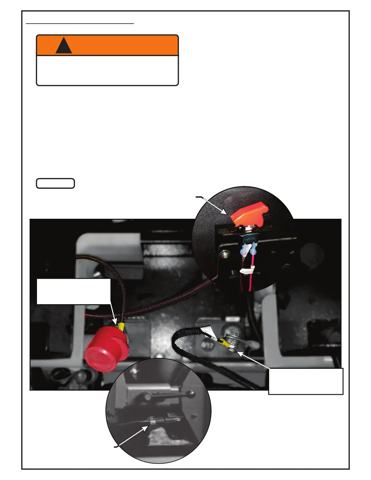
Wiring Harness Installation
Route the 2 Way Metri-Pack Connector (P#P0280) around the
right side of the engine and down between the side of the ROPS
to the right of the Right Mount Plate connecting the Quick
Connect Plug (#1) located on the PTO Drive. Refer to Figure A.
WARNING
!
To Prevent Serious Injury-
Proper Installation Of Safety Interlock Harness
Is Mandatory. Please Check That All Interlock
Points Work Correctly Once Installed.
Insert the PTO Switch in and through the PTO
Switch Bracket (P#B1020) then attach and secure
the Safety Cover (P#P0073).
Before routing the PTO Switch (#2), locate and
loosen the existing cap head screw located on the
bottom right side of the mower’s control panel.
Attach the PTO Switch Bracket by sliding it behind
the cap head screw and tightening the screw. Refer
to Figure A. (Note: This is the recommended
positioning of the PTO Switch, the PTO Switch
could be mounted anywhere within reasonable
distance and clearance to the right of the operator’s
seat)
Use the zip ties (P#J0245) that are provided to
secure the wires in place.
Route the PTO Switch to the positive terminal of the
battery (#3) using the Ring Terminal (P#P0086) of
the Positive Lead to secure the attachment. Route
the Negative Lead to the engine block (#4) using
the Ring Terminal of the Negative Lead to secure
the attachment. Refer to Figure A.
(#1) Quick Connect Plug
(#2) PTO Switch
Figure A
(#3) Positive (+) Terminal
Connection
(Battery)
(#4) Negative (-) Terminal
Connection
(Battery)