14
PTO Drive Assembly
Once the Mount Arm Assembly is installed and secured to the mower, assemble the Drive Assembly
P#(A2061_01), Belt Guard Assembly P#(A2069_02) & Idler Mount Assembly P#(A2067_02).
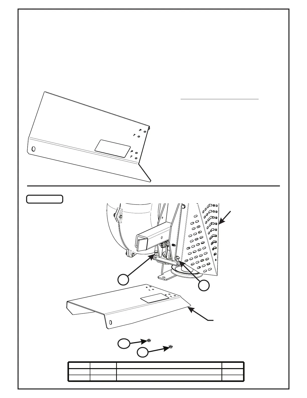
First, attach the Belt Guard Assembly P#(A2069_02) to the Drive Assembly P#(A2061_01) using (2) 1/4”-20 x 5/8”
Carriage Bolts P#(K1010) and (2) 1/4”-20 Ny-Flange Lock Nuts P#(K2014). Refer to Figure A. Leave Bolts
Loose.
Notice Marked Holes Below;
For This Installation, Use Holes
Marked With The Letter ‘P’
BELT GUARD ASSY. HOLES
Item # Part # Desc. Qty.
1 K1010 1/4"-20 x 5/8" Carriage Bolt 2
2 K2014 1/4"-20 Ny-Flange Lock Nut 2
1
1
Belt Guard
Drive Assembly
2
2
Figure A