Add: Building A, Xinlida Industrial Park, Junzibu Village,Guanlan Street, Longhua District ,Shenzhen,
Guangdong
TEL :0755-23225527 FAX:0755-23225537
14
5.2 Cable & circuit breaker requirement
• PVINPUT
Models Cable Diameter Max. PV Input Current Circuit Breaker Spec
5mm²/10AW
TEZE-AO-MB51300/400-AC380V
-10KW
G 22A 2P-25A
• AC INPUT
Models Output mode Max. Input Current Cable diameter
Circuit Breaker
Spec
Three-phas
TEZE-AO-MB51300/400-AC380V
-10KW
e 29A 7mm²/8AWG(L1/L2/L3/N) 4P-40A
• BATTERY
Models
Cable Diameter
Maximum charge
current
Circuit Breaker Spec
42mm²/1AW
TEZE-AO-MB51300/400AC-380V
-10KW
G 220A 2P-250A
• AC OUTPUT
Models Output mode Max. Input Current Cable diameter
Circuit Breaker
Three-phas
TEZE-AO-MB51300/400-AC380V
-10KW
e 14.5A 7mm²/8AWG(L1/L2/L3/N) 2P-63A
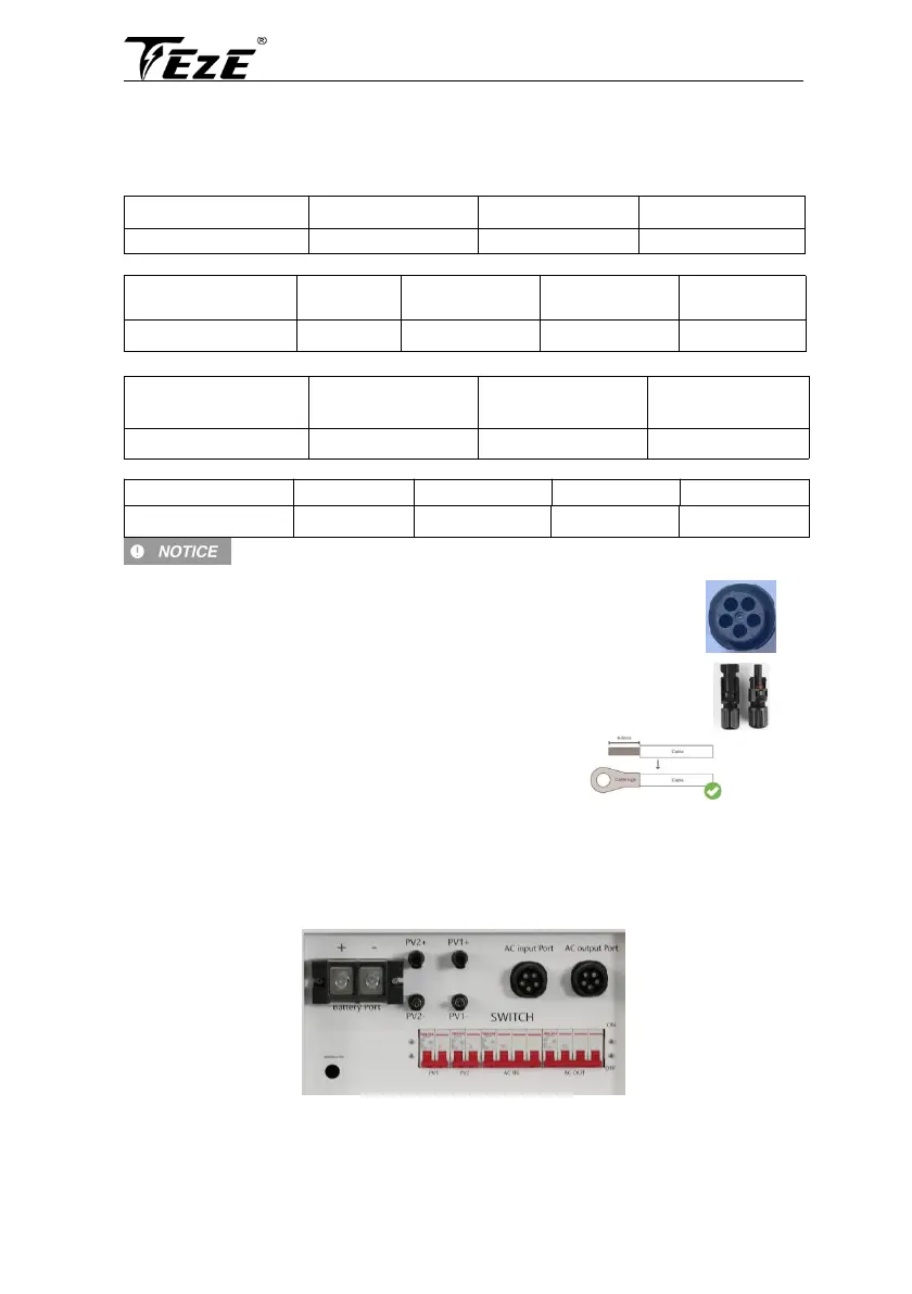
• AC INPUT、AC OUTPUT
Connect the marked L1 L2 L3 N PE according to the recommended wire diameter in
5.2, and then plug the 5-hole AC plug into the AC socket on the all-in-one machine
PV INPUT、PV OUTPUT
Connect the appropriate wire according to the recommended wire diameter in 5.2
BATTERY
1. Use a stripper to remove the 6~8mm insulation of the cable.
2. Fixing cable lugs that supply with the box at the end of the cable.
The wire diameter is for reference only. If the distance between the PV array and the inverter or
between the inverter and the battery is long, using a thicker wire will reduce the voltage drop and
improve the performance of the system.
5.3 AC input & output connection
Connect the live, neutral and ground wires according to the cables’ position and order shown in the
diagram below.