Add: Building A, Xinlida Industrial Park, Junzibu Village,Guanlan Street, Longhua District ,Shenzhen,
Guangdong
TEL :0755-23225527 FAX:0755-23225537
9
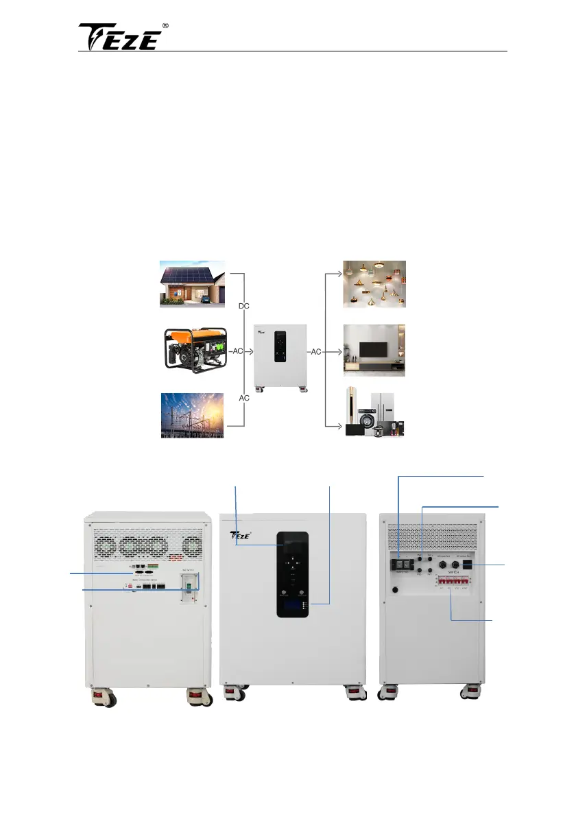
2.3 System connection diagram
The diagram below shows the system application scenario of this product. A complete system consists
of the following components:
1. PV modules: converts light energy into DC energy, which can be used to charge the battery via
an inverter or directly inverted into AC power to supply the load.
2. Utility grid or generator: connected to the AC input, it can supply the load and charge the
battery at the same time. The system can also operate generally without the mains or
generator when the battery and the PV module power the load.
3. Battery: The role of the battery is to ensure the regular power supply of the system load when
the solar energy is insufficient and there is no mains power.
4. Home load: Various household and office loads can be connected, including refrigerators,
lamps, televisions, fans, air conditioners, and other AC loads.
5. Inverter: The energy conversion device of the whole system.
The actual application scenario determines the specific system wiring method.
2.4 Production Overview
Communicati
on Interface
Air Switch
Inverter Display
Battery Display
PV Connector
Battery
Connector
AC Connector
Air Switch