AS 680/682
Description, Operation and Maintenance Maintenance and Repair
ADS−B
7−3Ed. 10.07
7.1.6 Preventive Exchange of Fan Unit
As preventive measure it is recommended to replace the fan unit in the SPU after about 2 years.
Tools required: Philips Screw Driver #2
Replace the Fan Unit as follows (see also section 7.3.3.6):
a) Switch off DC of the Ground Station (recommended: change without GS switch off also possible).
b) Unfasten the four captive screws fixing the Fan Unit.
c) Extract the Fan Unit carefully from the 19" subrack until the DC supply cable with the connector
is visible. Press the lock of the fan supply cable connector and remove it from the cable to the mo-
therboard.
d) Connect the connector of the spare Fan Unit to the supply cable to the motherboard until it locks.
e) Carefully insert the new Fan Unit into the slide. Take care not to squeeze the supply cable. Fasten
the four captive screws.
f) Switch on DC of the Ground Station.
7.1.7 Check and Adjustment of SPU/RXU local Oscillator Frequency
As preventive measure it is recommended to perform a check and if necessary a corrective adjust-
ment of the local oscillator frequency of the RXU subassembly in the SPU.
Tools required: Philips Screw Driver #2, Maintenance Adapter,Digital Multimeter, RF−Generator
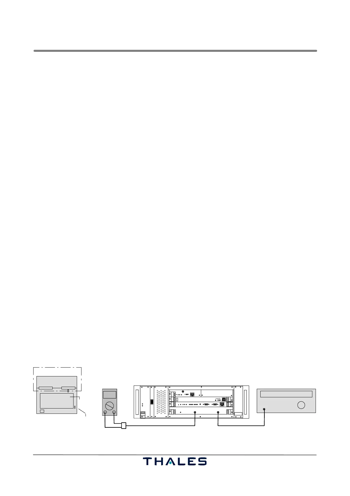
Perform the following procedure to check the frequency (refer to Fig. 7−1):
a) Switch off the Ground Station. Remove RF cable from connector RF In.
b) Remove the RXU board, and insert the RXU again plugged on a maintenance adapter. Open
jumper X3 (RXU1) or X1 (RXU2).
c) Connect the RF Generator to connector RF In; connect Digital Voltmeter to connector Monitor Out.
d) Set RF Generator to apply an RF signal of 1090 MHz and P= −80 dBm to connector RF In.
NOTE: The LO frequency will be calculated as f
lo
= f
in
− 60 MHz; this is 1030 MHz.
e) Switch on the Ground Station.
f) Vary the RF frequency about ±3 MHz at the RF generator to get a maximum DC voltage reading
at the Digital Voltmeter. The maximum should be within 1089 to 1091 MHz.
RXU1, Ref. No. 83142 71502, only: If not, an adjustment of the local oscillator frequency (LO) on
the RXU1 is required. Perform procedure in 7.1.7.1.
g) Switch off the Ground Station. Remove measuring cables. Withdraw RXU board. Set X3 (RXU1)
or X1 (RXU2) again. Insert RXU board and connect RF cable as normal again.
I
0
Monitor Out
1090 MHz
000.0
Digital voltmeter RF generator
RF In
Adapter cable SMA/BNC/Banana plug
SPU
Cable SMA/SMA or adapter SMA/BNC
RF out
SPU
RXU
RXU, plugged on
top view
maintenance adapter
X3 (RXU1)
shielding
cover
or
X1 (RXU2)
Fig. 7−1 Test setup frequency check of local oscillator of RXU subassembly
 Loading...