AS 680/682
Installation and Setup Description, Operation and Maintenance
ADS−B
3−4 Ed. 10.07
1 1
1
2
3
4
5
6
7
8
1
2
3
4
5
6
7
8
GND
T2OUT
T1OUT
R1IN
R2IN
GND
GND
T2OUT
T1OUT
R1IN
R2IN
GND
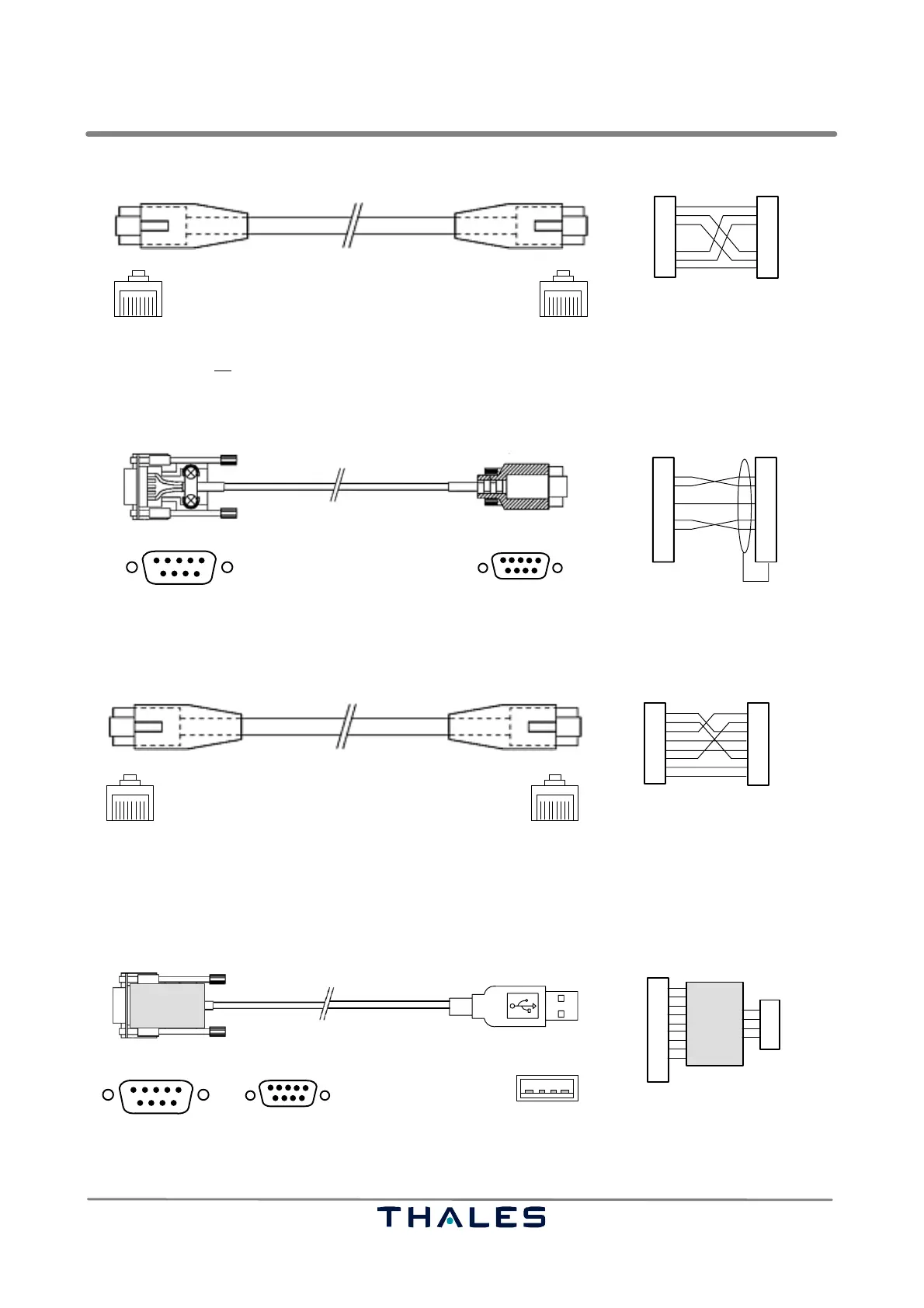
RJ45 8/8
approx. 2 m
RJ45 8/8
LiYCY 8x0.14
GS B /SPU B, SPB J6 BITE
GS A/SPU A, SPB J6 BITE
front view front view
NOTE: This is not an Ethernet cable ! Standard colour: grey.
Fig. 3−5 24028 28002, BITE connection cable, RJ45, 8/8 to RJ45, 8/8, crossed
1
5
SubD, 9pin, male
MicroSubD, 9pin, male
6
1
5
6
1
2
3
4
5
6
7
8
9
1
2
3
4
5
6
7
8
9
Shield
RxD
TxD
GND
RTS
CTS
RxD
TxD
GND
RTS
CTS
approx. 2 m
LiYCY 8x0.14
front view front view
NOTE: Used, if also a maintenance data terminal , e.g. as LCMS, shall be connected to configure e.g. Site Monitor.
Fig. 3−6 24028 28003, LCMS serial cable, SubD/9pin to MicroSubD/9pin, crossed
1 1
1
2
3
4
5
6
7
8
1
2
3
4
5
6
7
8
not used
TXD+
TXD−
RXD+
RXD−
RJ45 8/8
approx. 1.8 m
RJ45 8/8
LiYCY 8x0.14
GPS receiver, auxiliary Ethernet interface
LCMS
front view front view
not used
not used
not used
not used
RXD+
RXD−
TXD+
TXD−
not used
not used
not used
NOTE: Standard colour: yellow
Fig. 3−7 24028 28004, LCMS Ethernet cable (standard), 10/100Base−T, RJ45, 8/8, cross over
approx. 300 mm
Serial to USB
converter
1
1
5
SubD, 9pin, female
6
1
2
3
4
5
6
7
8
9
RxD
TxD
GND
RTS
CTS
data−
data+
GND
Vcc+1
2
3
4
USB A, male
Converter
MicroSubD, 9pin, female
1
5
6
or
SPU RS232
Laptop USB
RI
DSR
DTR
DCD
Construction example !
front view
front view
Fig. 3−8 24028 xxxxx, LCMS Serial to USB adapter cable, SubD/9pin to USB A, optional
 Loading...