AS 680/682
Description, Operation and Maintenance Installation and Setup
ADS−B
3−5Ed. 10.07
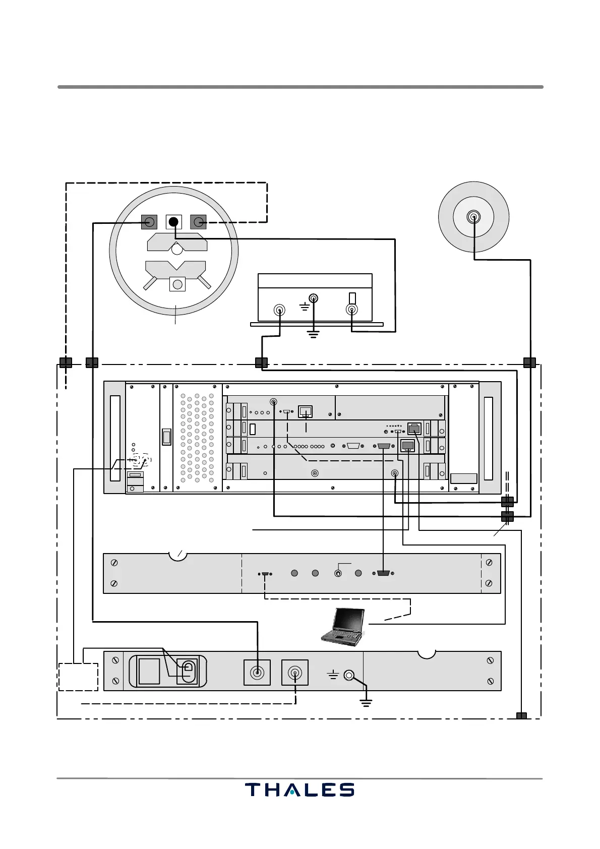
3.1.5 Interconnection of System Items
3.1.5.1 Ground Station AS 680
Fault
Power
THALES Mode S Ground Station SPU
SPBRXU
GTS
DG14
I
0
OL
M1 M2
ANTENNA
connector
RF test in from RF out2 of GS B/SM B,
ADS−B RX antenna A
AAU
RF out
+12V DC in
RF in
RF out 1** RF out 2**
DC in 24 V nom
GPS antenna A
bottom view
bottom view
SM, rear view (SM A)
RF test out to ADS−B RX antenna B/M2, option**
RF test out to ADS−B RX antenna A/M1
Power
THALES
ADS−B SITE MONITOR
MAINTENANCE TX FAULT STATUS
SM, front view (SM A)
pass through for antenna cables from SPU
Status Exchange to GS B/SPU B (option)
Ethernet
LAN
to RCMS
BITE signal
SPU, front view (SPU A)
local DC
supply
outdoor
indoor
20...28 VDC
LCMS
RF out
TNC
NNN
N*N*
LP=Lightning protection
SMA
SMA
* Connector definitions: N, SMA, TNC, N+LP, MicroSub
N+LP
N
N
N
N+LP
LP
N
N+LP
from
SM B
RJ45MicroSubD
MicroSubD
N
N
N
N
N
Exchange panel (option)
SubD15
SubD9
24028 28001
27288 04059
24028 28002
27288 04135
27288 04135
24028 28003
1)
1)
1)1)
1)
1)
1)
1)
1)
1)
1) 1)
opt. to LCMS
1)
PE
PE
1) Provided by customer
** if not connected to antenna, it must be terminated with 50 ohm
1)
not used
up to 30 m
up to 2m
up to 10 m
1)
up to 30 m
up to 30 m
option
to SPU or SM
NOTE:
RF cable to ADS−B antenna: 1/2" cellflex or similar
RF cable to GPS antenna: 1/4" cellflex or similar
24028 28004
RJ45
+
−
+
−
Fig. 3−9 System cabling ADS−B Ground Station AS 680 (one station shown)