AS 680/682
Description, Operation and Maintenance Installation and Setup
ADS−B
3−11Ed. 10.07
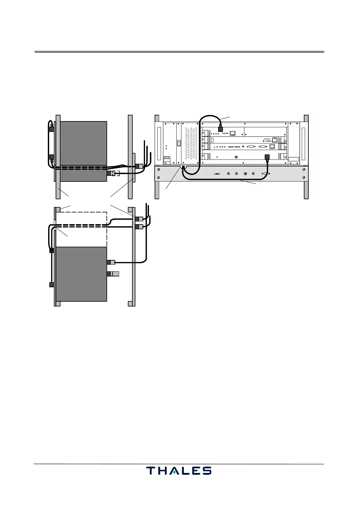
c) Mount the exchange panels at the back side of the rack (if possible) with the supplied mounting
material.
d) Connect the Ground Station ADS−B RF input (RXU) and the GPS antenna input (GTS) to the ex-
change panel by using the adapter cables 27288 04135; see also Fig. 3−15.
e) Connect the Ground Station to a DC supply (required connector: Molex 03−12−1026).
SM cable
SPU
I
0
THALES
THALES
GPS cable
ADS−B cable
SM
SPU
SM
Exchange Panel19" rack
50 ohms
load
RF OUT 1
RF OUT 2
GPS cable
ADS−B cable
SPU
SM
Top view
Side view, right hand rear
rear
front view
N/N
SMA/N
SMA/N
recess
recess
N/TNC
N/N
27288 04135
Fig. 3−15 Cabling and arrangement example of Exchange Panel
Mount the Site Monitor (SM A) in the provided rack:
a) Put the Site Monitor in the rack directly below the Ground Station and fix it with the supplied mount-
ing material.
b) The cable to the Exchange Panel (if used) shall be guided through the recess in the Site Monitor
front panel; see also Fig. 3−15.
c) Connect the SM status cable to the Ground Station status input (SPB) using cable 24028 28001
d) Connect the Site Monitor to DC supply (required connector: Molex 03−12−1026).
Mounting the second Ground Station (GS B), if intended: follow previous instructions for GS A.
Mount the second Site Monitor (SM B), if intended: follow previous instructions for SM A.
3.1.6.6.1 Installing the Cabling within the Shelter or Building (AS 680)
All inputs of the Ground Station and the Site Monitor provide secondary surge protection. They re-
quire primary protection means at the shelter entry point. All RF cables shall be as short as possible,
loops have to be avoided.