A80
INSTALLATION 0-4985
3-4
3.06 Gas Connections
Connecting Gas Supply to Unit
The connection is the same for compressed air or high
pressure cylinders. Refer to the following subsections if an
optional air line lter is to be installed.
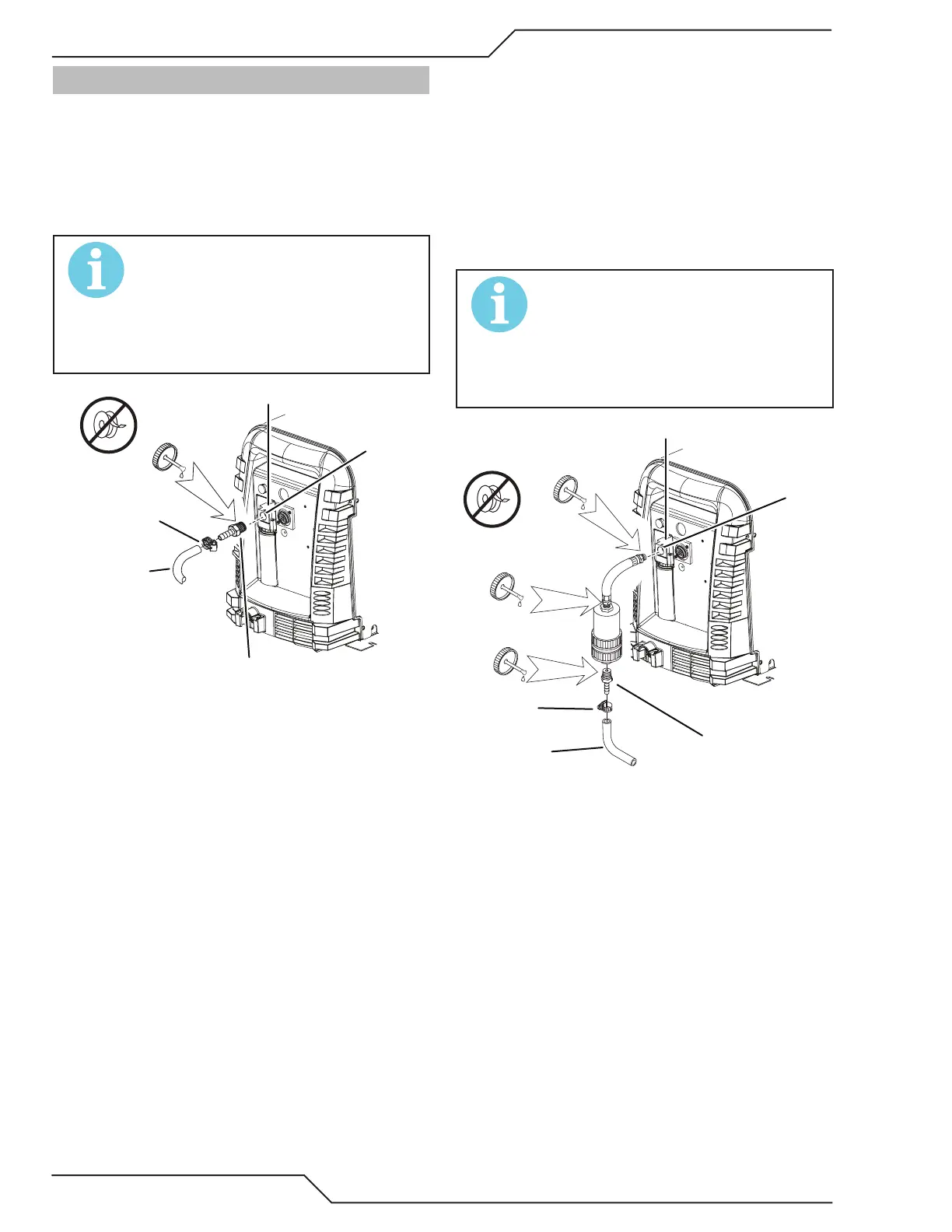
1. Connect the air line to the inlet port. The illustration
shows typical ttings as an example.
NOTE!
For a secure seal, apply thread sealant to the
tting threads, according to manufacturer's
instructions. Do not use Teon tape as a
thread sealer, as small particles of the tape
may break o and block the small air pas-
sages in the torch.
Art # A-08320
Inlet Po
Hose Clamp
1/4 NPT or ISO-R
Air Connection to Inlet Port
Installing Optional Single - Stage Air Filter
An optional lter kit is recommended for improved lter-
ing with compressed air, to keep moisture and debris out
of the torch.
1. Attach the Single - Stage Filter Hose to the Inlet Port.
2. Attach the Filter Assembly to the lter hose.
3. Connect the air line to the Filter. The illustration
shows typical ttings as an example.
NOTE!
For a secure seal, apply thread sealant to the
tting threads, according to manufacturer's
instructions. Do not use Teon tape as a
thread sealer, as small particles of the tape
may break o and block the small air pas-
sages in the torch. Connect as follows:
p
1/4 NPT to 1/4"
(6mm) Fitting
Inlet Po
Gas Supply
Hose
Optional Single - Stage Filter Installation